
Indirect Evaporating Cooling In The Passenger Car Air Conditioning System


Abstract
The passenger car air conditioning system is designed to supply and process fresh air, prevent it from the spread of infections and pathogenic bacteria through disinfection as well as provide com-fortable conditions for train passengers and personnel. The prime requirement for air conditioning systems in railway transport is the stability of parameters set to maintain microclimate in the train, regardless of meteorological conditions. One of the tasks facing the SLE in railway transport is to minimize the energy consumption of the air conditioner. This is due to the fact that a voltage of 220 V and lower is used to power the air conditioner, which can be obtained either from the contact network or from batteries on the train. Each kilowatt of low-voltage electricity is quite expensive, an order of magnitude more expensive than in a stationary location, and this is due to the increased attention to the energy consumption of SLE. The article proposes a method and conditions for calculating indirect evaporative cooling of passenger car air conditioning systems in order to reduce energy consumption, increase reliability and comfort of passenger transportation.
Keywords: Energy efficiency, Indirect evaporating heat exchanger, Passenger car air conditioning system
Introduction
To date, many people travel on long-distance trains. The air conditioning system in passenger cars is used to provide air with the required physical and chemical properties: temperature and humidity, oxygen and carbon dioxide content, dust content, etc. The refrigeration equipment of air conditioning units makes it possible to maintain the required temperature and humidity conditions in the car with the high ambient temperature and exposure to solar radiation.
Problem Statement
Most of the train cars that are in operation for a long time are equipped with freon air conditioning units, which have a number of disadvantages: large weight and dimensions; significant energy consumption; insufficient reliability and durability; struggle with ensuring complete sealing of the system due to the scattered units and long pipelines with a large number of connectors; a significant level of environmental pollution; harmful effect on human beings.
Research Questions
- How much heat is supplied to the passenger car?
- How to calculate the passenger car air conditioning system based on the method of indirect evaporating cooling?
Purpose of the Study
The main goal of this study is to design an air conditioning unit for a passenger car based on the indirect evaporating cooling method.
Research Methods
Heat engineering calculations of a passenger car
In order to determine the main characteristics of the air conditioning system based on the water indirect evaporating, it is essential to find the total amount of heat entering the car (Emelyanov et al., 2010). For this purpose, a heat engineering calculation has been carried out. The calculation is reduced to determine the total heat infiltrations into the car interior. The calculation scheme is shown in Figure 1.
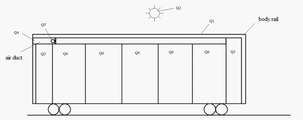
1 – the amount of energy entering the car through the body rails;2 – heat infiltration occurred in the result of exposure to solar radiation;3 – the amount of energy entering the car through leaks in the body;4 – the amount of energy entering the car with outdoor air in the result of cargo and passengers ventilation;5 – heat infiltration in the result of the fan motor operation;6 – heat infiltration from the passengers
Calculations of heat infiltrations are based on the following method:
The heat infiltration that occurs under the influence of the temperature difference is determined by the formula (2015):
,
where – temperature of outdoor air, in summer ;
– temperature of air inside the car, in summer;
– temperature of air in a car vestibule, in summer ;
– the area of the body rail which comes into contact with the outdoor air, ;
– the area of the body rail which comes into contact with a car vestibule rail, .
The heat infiltration from solar radiation is determined by the formula:
,
where the outer surface of the sunlit part of the car ( );
– solar energy absorption coefficient, accepted as 0.7;
– the average daily intensity of solar radiation, accepted as ;
– heat transfer coefficient of the outer surface, .
The heat infiltration through leaks in the doors, windows, etc. is determined by the formula:
,
where – the volume of air entering through the leaks, ;
– outdoor air density, in summer ;
1,2 – heat content of the air outside and inside the car , ;
The heat infiltration during the ventilation of the car is determined by the formula:
,
where – ventilation rate, 4 volume/hour;
– volume of air to be replaced, ;
– air heat capacity, ;
– absolute humidity of the air, ;
– latent heat of steam generation, .
The heat infiltration which is equivalent to the operation of the fans is determined by the formula:
,
where – fan motor power, ;
– the number of motors, ;
– efficiency of motors, ;
– duration of electric motor operation, ;
Heat infiltrations from the transported cargo and containers during cooling in the car:
,
where – the amount of energy released by one passenger, W;
– the number of passengers, ;
The calculation results are summarized in Table 1.
The total heat infiltration to the passenger car interior is determined:
To perform calculations of an air conditioning system with indirect evaporating cooling, it is essential to find out the maximum values of heat infiltration – «gross»:
,
where – a coefficient that takes into account inaccuracy of the calculation, 1,15.
After calculating the total heat infiltrations, it is possible to calculate the system of indirect evaporating cooling of the passenger car air.
Calculation of indirect evaporating cooling
Direct evaporating cooling has different design schemes:
- indirect evaporating cooling system without water circuit (Figure 2a);
- indirect evaporating cooling system with a water circuit (Figure 2b).
In an indirect evaporating cooling system, the ambient air is blown into the system by a fan and is cooled to a constant moisture content in the indirect evaporating heat exchanger. After the heat exchanger, the main air flow is divided into two parts: secondary and operating, which is directed towards absorbing part of the system (Emelyanov & Gorbatov, 2013).
The secondary flow is a cooler and a cooling flow at the same time - after the heat exchanger, it is directed back towards the main flow. In this case, the water is supplied to the secondary flow ducts. Relevance of water supply is to slow down the growth of air temperature due to its parallel humidification: the same change in thermal energy is known to be achieved by changing the temperature as well as by simultaneously changing the temperature and humidity. When the secondary flow is humidified, the same heat exchange is achieved with a smaller temperature change.
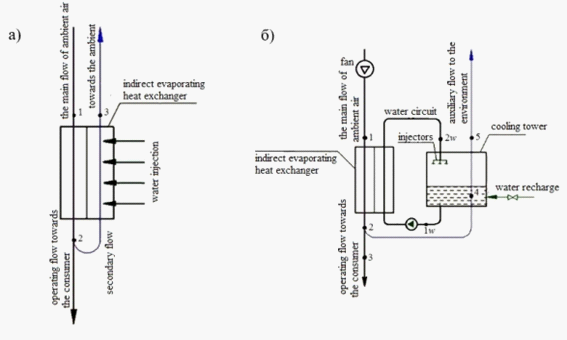
In the case of indirect evaporating heat exchangers of a different type, the secondary flow is not directed to the heat exchanger, but to the cooling tower, where it cools the water circulating through the indirect evaporating heat exchanger: the water is heated by the main flow, flows in the flow and is cooled in the cooling tower by the secondary air flow. A circulation pump helps the water go along the circuit.
To calculate the cycle of an indirect evaporating cooling system with circulating water, the following initial data are used:
–a – relative humidity of the ambient air, 55%;
–a – temperature of the ambient air, 30° С;
– – temperature difference at the cold end of the heat exchanger, 3° С;
–w – temperature difference at the warm end of the heat exchanger, 5° С;
–ct – the difference between the temperature of the water coming out of the cooling tower and the temperature of the air supplied to it by a wet bulb thermometer, 1° С;
– – minimum temperature difference (temperature head) between the flows in the cooling tower (∆tmin <∆twct), 2° С;
–р – mass air consumption required by an absorbing part of the system, 9,89 kg/s;
–f – Fan efficiency, 0,7%;
–f – pressure loss in the system mechanism and lines (required fan head), 680 Pa.
The calculation method is based on the following assumptions:
– The processes of heat-mass transfer are balanced,
– There is no external heat infiltration on all areas of the system,
– The air pressure in the system is equal to atmospheric (local changes in air pressure due to air being moved by a fan or due to the fact that its circulation through aerodynamic drag is small, which makes it possible to use of I-d diagram moist air to atmospheric pressure throughout the whole circulating system).
Engineering calculation
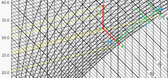
The sequence of engineering calculations of the system is as follows (Figure 3) (2012).
Additional parameters of the ambient air (point "0" in Figure 3) are determined using the I-d diagram or using the humid air calculation program: the specific enthalpy of the air i0, J / kg and the moisture content d0, kg/kg.
The increment of the specific enthalpy of air in the fan (J/kg) depends on the type of fan. If the fan motor is not blown (not cooled) by the main air flow, then:
wherem – motor efficiency;
– air density before entering the fan, kg/m3
– barometric pressure of the environment, Pa;
a – the gas constant of the air is equal to 287 J/(kg•K).
The increment of the specific enthalpy of air in the fan
Specific enthalpy of air which comes out of the fan (point «1», Figure 3), J/kg.
i1= i0+∆ia
Since the process (0 – 1, Figure 3) occurs at a constant moisture content (), it is possible to determine the air temperature that comes out of the fan (point 1, Figure 3) from the known values of.
The dew point of the ambient air is determined by the known value of,.
Psychrometric temperature difference of the main flow air that comes out of the heat exchanger (point 2, Figure 3) is, °С
∆t2–4=∆tx+∆twct
where ∆tх is assigned based on the specific operating conditions in the range (0.5...5.0), °C. At the same time, small values of ∆tх will entail a relatively large size of the heat exchange unit. To ensure low values of ∆tх, it is crucial to use highly efficient heat transfer surfaces;
ct is selected in the range (0.8 - 3.0), °C; lower values ofгр should be taken if it is necessary to obtain the lowest possible temperature of cold water in the cooling tower.
The humidifying process of the secondary air flow in the cooling tower from state 2-4 (Figure 3), with sufficient accuracy for engineering calculations, should go along the line.
In this case, with the value ∆t2–4, the temperatures andcould be determined, points 2 and 4, respectively, °C. To do this, a line such that the temperature difference between point 2 and point 4 corresponds to the foundshould be found. Point 2 is located at the intersection of the lines and the constant moisture content. Point 4 is located at the intersection of the line and the curve = 100 % of relative humidity (2021).
Thus, with the help of the above diagrams, it is possible to determine the remaining parameters at points 2 and 4 (Figure 3).
It is possible to determine the temperature of the water that comes out, at the point 1w, °C. In the calculations, the heating of the water in the pump can be neglected, therefore, before entering the heat exchanger point 1w (Figure 3) the water will have the same temperature
t1w=t4+∆twct
It is necessary to determine– water temperature after heat exchanger, point 2w, °С
t2w=t1-∆th=
The temperature of the air discharged into the water tank point 5 is determined semigraphically using the I-d diagram. The specified method is as follows (Figure 3).
The point 1w, which characterizes the state of water at the entrance to the indirect evaporating heat exchanger, with the value of the specific enthalpy of point (4) is placed on the isotherm t1w, which is separated from the isotherm t4 at a distance ofct.
From the point 1w along the isentalpa, the segment 1w — is set so that. According to the fact that the process of heating the air in the cooling tower occurs100 %, from the point «p» a tangent toпр=1 is drawn so that the point of tangency is now found out.
From the point of tangency along the isentalpa (adiabat,) the segment - is drawn so that. Thus, the minimum temperature difference between the cooled water and the secondary flow air in the cooling tower is provided. This temperature difference guarantees the operation of the cooling tower in the design regime. Now it is necessary to draw a straight line from point 1w through point n to the intersection with the straight line so that the point 2w is known. From point 2w, a straight line to the intersection withпр100% is drawn. Point 5 which characterizes the state of the air coming out of the cooling tower is known.
According to the diagram (Figure 3), the required temperature t5 and the other parameters of point 5 can be found.
The air parameters obtained in the result of calculations and drawing:
– air temperature after the fan (32 °C);
– secondary flow temperature before entering to the cooling tower (26°C);
– secondary flow temperature in the cooling tower (20.5°C);
– temperature of the air that comes out of the cooling tower (25.5°C).
Thus, it is possible to compose a system of equations to find unknown mass flow rates of air and water. Thermal load of the cooling tower on the secondary air flow, W:
Qct=Ga ( i5 – i2)
Wherea – secondary air mass flow rate, kg/s
Thermal load of the cooling tower by water flow:
Qwct=Gow Cpw ( t2w – t1w) =
Wherep specific heat of water, 4200J/(kg•K)
– material balance by air flow
Heat load of the heat exchanger in the main air flow, W:
Qhl=Go( i1 – i2)
Heat load of the heat exchanger in the water flow, W:
Qwht=Gow Cpw ( t2w – t1w)
Cooling tower heat balance:
ct ct
Combined heat balance of the cooling tower and the water heat exchanger:
Qwct=Qwhl
Air mass flow rate in the main air stream, kg/s:
Go=Gr
Water mass flow rate through the cooling tower along the main stream, kg/s:
The amount of water required to recharge the cooling tower water circuit, kg/s
Gwr=(d5-d2)Gw
Thus, all the required parameters for the design calculations of the elements of the indirect evaporating air cooling system are found.
The working flow of cooled air supplied to the absorbing part of the system which is point 2 (Figure 3) can be additionally cooled, for instance, by adiabatic humidification or by any other method. As an example, Figure 3 shows the point 3* corresponding to adiabatic moisture. In this case, the points 3* and 4 match (Figure 3).
Findings
Based on the method of indirect water evaporation, a passenger car air conditioning system has been developed (Figure 4).
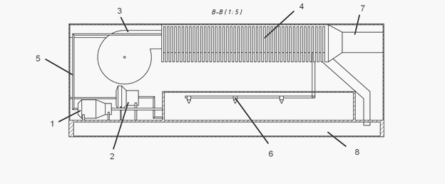
Based on the results obtained, the main equipment of the projected air conditioning system has been selected.
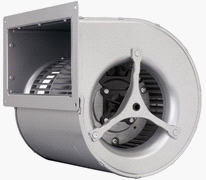
The Salda VR 355-4 L3 double-suction centrifugal fan (Figure 5) has a rotating rotor consisting of spiral-shaped blades. The air is forced through the inlet into the rotor, where it acquires a rotational motion and, due to the centrifugal force and the special shape of the blades, is directed to the outlet of a special spiral casing. The maximum capacity of such a fan is 5800 m³/h. Power is 3000W .
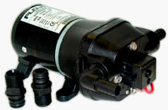
The pump for moving water from the water supply system from is designed by Flojet (Figure 6) with a capacity of 12 l/min. The maximum pump power is 0.7 kW.
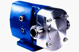
The pump for supplying water to the SRU series injectors (Figure 7) is capable of providing flow rates of up to 106 m3/h and a pressure of up to 8 bar. The maximum pump power is 1.5 kW.
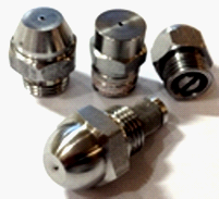
In order to humidify the air, the injectors have been selected. They are designed for high-quality fine spray of water and any liquids. The micro-flow injectors are assembled with a filter element. Fog type injectors (Figure 8) are produced with small and extremely small flow characteristics from 1 l/h to 30 l/h at a water supply pressure from 2.0 to 18.0 bar, with spray angles from 60 to 90 °C.
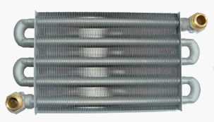
To cool the main flow air in the indirect evaporating cooling system, a heat exchanger has been selected (Figure 9). The tubular heat exchanger is designed to transfer heat energy from the warm outdoor air to the cooled water through the walls of the tubes. Due to this, the air will be cooled and will be delivered to the absorbing system at the set temperature.
Based on the results of the calculations and selection of the main equipment of the indirect water evaporating system for the passenger car, the total energy consumption of the installation amounts to 6200 W.
Conclusion
The calculations show that the installation of air conditioning with indirect evaporating air cooling system requires less electricity than freon system as well as it does not pollute the environment and does not have a harmful effect on human beings.
The implemented method of air conditioning with indirect evaporating cooling is more energy efficient than the outdated freon air conditioning units of train cars that are in operation for a long time. In case of exposure to uncomfortable external conditions, the power of system may not be enough. To solve this problem, it is essential to use a supporting air cooling stage, for example, a thermoelectric one.
References
Emelyanov, A., & Gorbatov, K. (2013). Isparitelno-kompressionnaya ustanovka kondicionirovaniya vozduha [Evaporative-compression air conditioning unit: Textbook-method. Allowance]. NRU ITMO; IHiBT, 35.
Emelyanov, A., Kozin, V., & Tsar, V. (2010). Energosberegayushchie sistemy kondicionirovaniya i ventilyacii passa-zhirskih vagonov [Energy-saving air conditioning and ventilation systems for passenger cars]. Transport of the Russian Federation Magazine, 4, 29.
Faerstein, Y., & Kitaev, B. (2015). Air conditioning in passenger cars. Transport of the Russian Federation Magazine, 272.
Homutskij, U. (2012). Sistemy kondicionirovaniya v poezdah [Air conditioning systems in trains]. Climate World Magazine, 71, 47
Krasnichenko, A., Gashin, D., & Kolesnyak, A. (2021). Thermoelectric cooling as an element of improving the comfort of passenger cars. [Scientific almanac of the Central Chernozem region], - Kursk.: 1, 25-33.
Copyright information

This work is licensed under a Creative Commons Attribution-NonCommercial-NoDerivatives 4.0 International License.
About this article
Publication Date
21 January 2022
Article Doi
eBook ISBN
978-1-80296-954-2
Publisher
European Publisher
Volume
1
Print ISBN (optional)
-
Edition Number
1st Edition
Pages
1-333
Subjects
Biotechnology, ecology, water, toxicants, nature management
Cite this article as:
Krasnichenko, A. A., Gashin, D. P., Alexandrov, D. E., Larkin, A. D., & Goncharov, D. G. (2022). Indirect Evaporating Cooling In The Passenger Car Air Conditioning System. In S. V. Beketov, & I. A. Nikitin (Eds.), Biotechnology, Ecology, Nature Management, vol 1. European Proceedings of Life Sciences (pp. 86-97). European Publisher. https://doi.org/10.15405/epls.22011.10