Indirect Evaporating Cooling In The Passenger Car Air Conditioning System
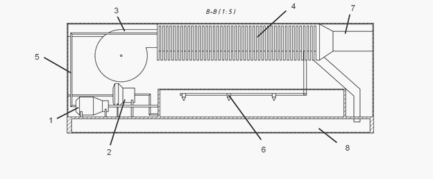
Figure 4: Schematic diagram of the installation of indirect water evaporation for the air conditioning system of a passenger car. 1 – a pump (which creates pressure when water is supplied to the injectors); 2 – a pump that moves water from the water supply system to the tank; 3 – centrifugal fan; 4 – heat exchanger; 5 – water supply pipe from the pump to the injectors; 6 – injectors; 7 – air distribution tool; 8 – water tank.
< Back to article