Indirect Evaporating Cooling In The Passenger Car Air Conditioning System
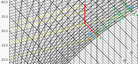
Figure 3: Semigraphical method in order to determine the parameters of the air emitted from the cooling tower in the indirect evaporating air cooling system, with the use of the I-d diagram. 0 – ambient air condition; 1 – air, after passing through the ventilation unit; 2 – air condition in the passenger interior of the car; 3, 4 – air condition in the cooling tower; 5 – air released into the atmosphere after the heat exchange process in the cooling tower
< Back to article

