
Simulation Of The Electromechanical Device Response To Vibration Impact


Abstract
The article describes a simulation model of a double electromagnet under the influence of random vibrations on the yoke. The Simscape module toolkit was chosen as the modelling environment, which allows modelling phenomena of a multiphysical nature. It has been experimentally shown that combinations of system parameters are possible, leading to a decrease in the vibration effect on the rocker. During transients, high voltage is induced in the elements of the electric circuit of the electromagnet, which can lead to damage to the components of the electromagnet. It is determined that by choosing the appropriate parameters of the system, it is possible to prevent resonant states. The boundary values of the currents in the electromagnet winding are determined, at which the effect of "sticking" of the yoke to the main magnetic circuit occurs. Amplitude-frequency dependences are obtained for various values of direct current. The eigenfrequencies of oscillations of the investigated electromechanical system are determined.
Keywords: Electromagnet, multiphysics system, natural frequency shift, simulation experiment, vibration effects
Introduction
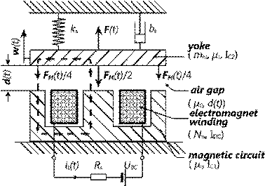
The paper considers the reaction of an electromechanical system (double electromagnet) to random vibrations. Figure 1 shows the investigated electromechanical device - an electromagnet with a W-shaped magnetic circuit, which is closed by a movable yoke. The yoke is subject to vibrational mechanical stress. The changing air gap between the main magnetic circuit and the yoke is the cause of variable reluctance, which affects the magnetic flux and, accordingly, the force of attraction of the yoke to the magnetic circuit. The non-linear nature of the magnetizing force leads to mechanical vibrations of the yoke.
According to Faraday’s law of electromagnetic induction (Darula et al., 2011), the change in magnetic flux that occurs when the magnetic resistance changes, induces an alternating voltage in the winding of the electromagnet, which is the reason for the superposition of currents (direct and alternating) flowing through the winding.
Problem Statement
At present, in connection with the development of robotic devices, the task of assessing the reliability of the operation of these devices under vibration conditions becomes more and more urgent. Three approaches are possible here:
1. Use valid device models.
2. Use mathematical simulation models.
3. Combined combination of the first two approaches.
From the point of view of efficiency and reliability, the combined approach is most preferable, but this method requires large material and time costs in comparison with the second approach.
In our work, we consider the second approach as the main approach to the study of the processes occurring in electromechanical devices during their operation under vibration conditions (Afanasyev & Borisova, 2016).
Research Questions
It is necessary to answer the question of the possibility of determining emergency conditions based on the proposed mathematical Simulink model (Neyman & Neyman, 2016a; 2016b)
Purpose of the Studу
During the study, it is necessary to determine the possible combinations of parameters of the electromechanical system leading to stable states (Neyman et al., 2020).
Determine combinations of parameters leading to unstable states up to device failure (Sattarov et al., 2019; Song et al., 2020)
Research Methods
To analyse the phenomenon under study, a lumped-parameter model built in the MATLAB Simscape block-visual modelling environment was adopted as a mathematical one (Mathworks, 2021).
The behaviour of the system is considered in the time domain, so the parameters are either constant or time-dependent (Villwock & Pacas, 2009; Sato et al., 2016).
Parameter values are selected based on data obtained for a real operating device.
Mathematical modelling
The mathematical model is presented in the form of a synthesis of three subsystems, schematically shown in Figure 2.

Let's consider each of the subsystems separately and their interaction with each other.
Magnetic subsystem
The magnetic subsystem consists of 3 main elements:
- source of magnetic flux– coil with electric current ;
- magnetic resistance of the air gap with constant and variable components ;
- magnetic resistance of the magnetic circuit .
According to Ampere’s law, the magnetomotive force is determined by the equation:
,(1)
here – is the vector of the magnetic field strength, – is the vector of elementary displacement along the integration contour C, marked in Figure 1 with a dashed line. From Figure 1 follow that contour integral can be represented as:
,(2)
here – is the average length of the magnetic flux path
For simplicity, we will assume that the cross-sectional area of the magnetic circuit and the air gap are the same. Then, for magnetic flux density (magnetic induction ) and magnetic field strength ( ) we obtain, for magnetic circuit and for air gap, substituting (2) into (1) we arrive at the result (Zakaria, et al., 2010):
,(3)
therefore, the following relation is valid for the magnetic field induction:
,(4)
where - is the length of the path of the magnetic flux in the core of the magnetic circuit and along yoke. We consider the magnetic permeability of the material of the yoke and the magnetic circuit to be the same. (Tatevosyan, et al., 2018).
Electrical subsystem
For the sake othe f simplicity, we neglect the losses in the voltage source, i.e., direct voltage source is ideal. Active resistance of the winding is taken equal to the resistance at direct current. Thus, almost all energy is released in the shut resistor . Applying the second Kirchgoff’s law for mesh, shown in Figure 2(b), we obtain the following relationship:
,(5)
where – is the magnetic coupling. From equation (4) for magnetic field induction we obtain the following for the magnetic flux:
.(6)
Thus, the basic relationship for the electrical part of the subsystem can be written as:
.(7)
From this ratio, it can be concluded about the mutual influence of a time-varying air gap on the operation of the magnetization circuit and the mechanical subsystem (Azin, et al., 2017).
Mechanical subsystem
The mechanical subsystem is considered as a vibrational link with one degree of freedom.
External mechanical action is considered in the form of a time-depended force . The force of magnetic attraction of the yoke to the main magnetic circuit is denoted by .
According to Newton's second law, the equation of motion for the mechanical part can be represented as (Afanasyev & Borisova, 2016):
,(8)
here is the displacement of the yoke from the equilibrium position.
The expression for the force of the magnetic attraction can be obtained from Maxwell’s concept for the forces acting on bodies in a uniform magnetic field with induction:
(9)
Substitution expression for from (4) into (9) we get:
.(10)
From (10) it is proportional to the square of the total current , flowing through the winding of the electromagnet and, time-varying square of the air gap .
Substituting (10) to (8) we obtain the equation of motion for the mechanical subsystem:
(11)
Relation (11) shows that the electric magnetic subsystems mutually influence each other, i.e., relations (7) and (11) are interrelated.
Simulation model
The numerical implementation of the electromechanical device model is obtained in the form of a Simscape model, Figure 3 (Mathworks, 2021).
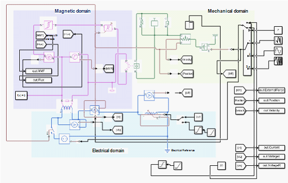
The “Variable Reluctance” and “Electromagnetic Converter” blocks represent converters, which are gateways that convert energy from one subsystem to another. Each physical subsystem is represented as a set of interacting blocks with lumped parameters. The model is calculated using a built-in constant step solver - ode14x, which combines Newton's method and extrapolation methods to calculate the solution in the next step.
The simulation experiment was conducted with three types of mechanical impacts:
- Random noise – to determine resonance conditions.
- Harmonic, sinusoidal action - to determine the parameters of the system states during transient processes.
- Sinusoidal with a linearly increasing frequency - to determine the conditions for eliminating the negative effect of transient processes on the system.
The numerical values of the parameters are presented in table 1.
Findings
A preliminary analysis of the system with the values of the parameters presented in table 1 shows that the natural frequency of the mechanical subsystem is close to 40 Hz. Since the frequency response of the system is of interest, a bandwidth of 100 Hz (Neyman et al., 2020) with a resolution of 0.25 Hz was chosen to apply the fast Fourier transform. The experiment uses a fixed time step of 0.001 s, the simulation time of transient processes is 7 s. In the case of a harmonic "chirp" (sinusoidal action with a linearly increasing frequency), the simulation time is 20 s.
According to (11), for the parameters given in table 1, the critical value of the constant component of the magnetizing current =0,427 А. To prevent the occurrence of the phenomenon of "sticking" of the yoke to the magnetic circuit, simulation tests were carried out for values of magnetizing currents not exceeding = 0.3 A.
The plots of the amplitude-frequency characteristics for different values of the DC components of the magnetizing currents when simulating a random mechanical effect on the yoke are shown in Figure 4.
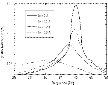
A noticeable shift in the natural frequency occurs at values . An increase in current has a damping effect on the system under consideration.
Figure 5 shows the yoke deviations from the equilibrium position and the induced voltage at a linearly increasing freque y of the external influence at = 2 kΩ.
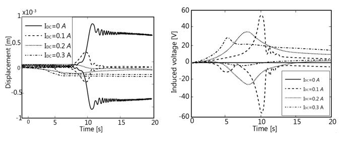
From the graphs of the yoke deflection and the induced voltage, the transient voltage, in the electrical circuit during initialization, is distributed smoothly without an abrupt change. This is a safer way to turn on the electromagnetic system than to suddenly turn it on (Sitnikov & Sepp, 2019a). The amplitude peaks at different values of the magnetizing current occur at different time intervals; therefore, this effect can be used to suppress vibration during the start-up of devices with similar types of electromagnets and to reduce the vibration amplitude when resonance passes. This circumstance is of interest from a practical point of view.
Conclusion
The paper considers a simulation model of an electromechanical system - an electromagnet with a movable yoke under vibration conditions.
It is shown that the multiphysics modelling of the system with lumped parameters in the time domain is consistent with the results obtained based on analytical calculations.
There are possible combinations of parameters: the width of the air gap – , the constant component o the magnetizing current – , the shunt resistance – at which the maximum attenuation of vibration processes is observed.
A numerical analysis of the switching on of the electromagnet during the vibration of the yoke shows that a large voltage surge in the electrical circuit is possible if the parameters are incorrectly selected (Sitnikov & Sepp, 2019b).
A simulation experiment based on Simscape (Mathworks, 2021) can serve as a tool for studying the operating parameters of the designed mechatronic devices, as well as for analysing transient processes in research objects.
References
Afanasyev, A. P., & Borisova, S. Yu. (2016). Modeling and analysis of the reaction of an electromechanical device to a random mechanical action. Sholom-Aleichem Priamursky State Bulletin, 4(24), 9-17.
Azin, A. V., Bogdanov, E. P., Ponomarev, S. V., & Rikkonen, S. V. (2017). Calculation of energy parameters of submerged vibrating confuser of an electromagnetic vibrator. Bulletin of the Tomsk Polytechnic University, Geo Assets Engineering, 328(5), 16–23.
Darula, R., Stein, G. J., & Sorokin, S. (2011). An Application of Electromagnetic Induction in Vibration Control. Proceeding of the 10th Int. Conf. on Vibration Problems, Springer Science, 447–453.
Mathworks: web page of MATLAB Simulink Simscape, on-line (2021). http://www.mathworks.com/products/simscape/ 2021
Neyman, L. A., & Neyman, V. Yu. (2016a). Dynamic model of an electromagnetic drive of oscillatory motion for systems for generating low-frequency vibrations. Reports of the Academy of Sciences of the Higher School of the Russian Federation, 3(28), 75-87
Neyman, L. A., & Neyman, V. Y. (2016b). Dynamic model of a vibratory electromechanical system with spring linkage. 11th International Forum on Strategic Technology, 23–27.
Neyman, L. A., Neyman, V. Y., & Markov, A. V. (2020). Mathematical model of the technological vibratory unit with electromagnetic excitation. Journal of Physics: Conference Series, 1661(1), 012063.
Sato, Y., Murakami, K., & Tsubo, Y. (2016). Sensorless Torque and Thrust Estimation of a Rotational/Linear Two Degrees – of – Freedom Switched Reluctance Motor. IEEE Transactions and Magnetics, 52(7), 8204504.
Sattarov, R. R., Enikeev, R. D., & Razyapov, M. V. (2019). Dynamics of fast-switching electrodynamic actuator for fuel injection in internal combustion engines. 13th International IEEE Scientific and Technical Conference Dynamics of Systems, Mechanisms and Machines Dynamics, 8944568.
Sitnikov, M. A., & Sepp, Yu. I. (2019a). The Effect of Main Contact’s Vibration in System “AC Switch Apparatus -Switched Device” on States of Switched Device, 2019 IEEE Conference of Russian Young Researchers in Electrical and Electronic Engineering, 686-690.
Sitnikov, M. A., & Sepp, Yu. I. (2019b). Influence of Contact Connection’s Vibration on Induction Motor’s Parameters under During Start-up. 2019 International Conference on Electrotechnical Complexes and Systems, 156676.
Song, Myeong-Ho, Xuan D. Pham, & Quang D. Vuong (2020). Torsional Vibration Stress and Fatigue Strength Analysis of Marine Propulsion Shafting System Based on Engine Operation Patterns. Journal of Marine Science and Engineering, 8(8), 613. DOI:
Tatevosyan, A. S., Tatevosyan, A. A., & Zaharova, N. V. (2018). Calculation of non-stationary magnetic field of the polarized electromagnet with the external attracted anchor. Journal of Physics: Conference Series, 1050(1) 012086.
Villwock, S., & Pacas, M. (2009). Time-domain identification method for detecting mechanical backlash in electrical drives. IEEE Trans. Ind. Electron., 56(2), 568-573.
Zakaria, Z., Mansor, M. S. B., Jahidin, A. H., Azlan, M. S. Z., & Rahim, R. A. (2010). Simulation of Magnetic Flux Leakage (MFL) Analysis Using FEMM Software. In Proceedings of the 2010 IEEE Symposium on Industrial Electronics and Applications, 481–486.
Copyright information

This work is licensed under a Creative Commons Attribution-NonCommercial-NoDerivatives 4.0 International License.
About this article
Publication Date
03 June 2022
Article Doi
eBook ISBN
978-1-80296-125-6
Publisher
European Publisher
Volume
126
Print ISBN (optional)
-
Edition Number
1st Edition
Pages
1-1145
Subjects
Social sciences, education and psychology, technology and education, economics and law, interdisciplinary sciences
Cite this article as:
Afanasyev, A. P. (2022). Simulation Of The Electromechanical Device Response To Vibration Impact. In N. G. Bogachenko (Ed.), AmurCon 2021: International Scientific Conference, vol 126. European Proceedings of Social and Behavioural Sciences (pp. 43-51). European Publisher. https://doi.org/10.15405/epsbs.2022.06.6