
Hydroelectrical Power Plant (Hpp) –Aspects Regarding The Operating And Maintenance Technologies

Abstract
This paper presents the hydroelectric power plant (HPP) types in order to focus the importance of using the hydraulic energy as a regenerative and never-failing alternative source of energy as well as a solution in regulating watercourses. The main constructive elements and their succession in the technological flow of water energy conversion into the final electrical energy are presented as well as a general classification of HPP from several points of view taking into account the most important classification criteria. Achieving a HPP on a water running course involves the construction of hydropower facilities. The hydropower development includes a complex of constructions and installations helping the watercourse hydraulic energy to concentrate and transform into electric energy. The main advantages are briefly exposed. The conversion of hydraulic energy into electricity is not polluting, involves relatively small maintenance costs, there are no fuel issues and it is a long-lasting viable solution. Although there are certain negative aspects that are not missing from this paper. The Voineşti hydro electrical power plant (HPP) is presented as a study case with its scheme and its main component elements. The specific maintenance operations are exposed on three main sections in a structural scheme and presented as such.
Keywords: Hydraulic energyhydroelectric power plantnot polluting energymaintenance technologies
Introduction
Currently, electricity is used in all domains of activity due to some main aspects: results from conventional sources of energy, such as potential energy from fuels, but also from renewable energy sources, such as hydraulic energy, atomic energy, wind energy, solar energy (Legendi & Bardescu, 2010); possibility to be transformed and used in other forms of energy (for ex.: mechanical form to drive mechanisms, etc.); easily transportable over long distances by wires/conductor cables.
The use of hydraulic power to produce electric energy has important benefits to take into account (Avram & Legendi, 2015):
• although limited, hydraulic energy is renewable and inexhaustible through the water circuit in nature;
• transformed into electric energy, ensures the energetic supply of localities in the neighbourhood ;
• the technologies used to transform hydraulic power in electricity are safe and of high efficiency;
• specific equipment is highly manoeuvrable in operating, ensuring easy take-up of load variations imposed by consumers (Figure
The Hydraulic Power Plant (HPP) classification.
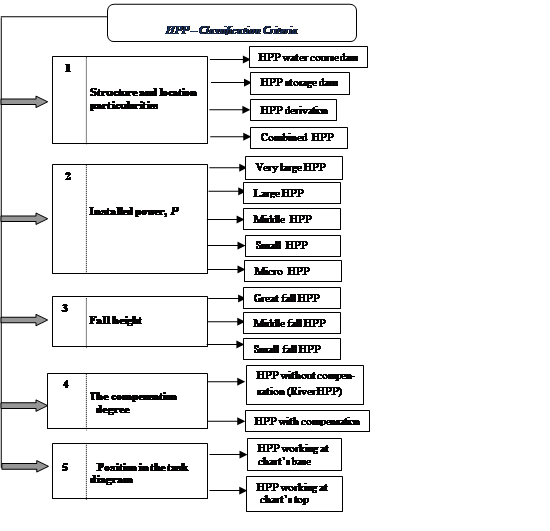
The HPP main constructive elements.
Hydropower plants (HPP) convert the water potential energy into mechanical energy through turbines and then through power generators (Figure
The main HPP constructive elements and their succession in the technological flow of water energy conversion into the final electrical energy are exposed in figure above and presented here below:
- storage lake (1)- is a hydropower harnessing and/or water management; realized by raising the water level over the natural one and retaining a certain water volume in order to ensure the time-division of the water flows distribution.
dam (2)- has the role of blocking a riverbed in order to obtain water accumulation, to create a level difference and deviate water towards capture facilities flooding valve–element that transitions the water from the reservoir (storage lake) to the adduction channel to provide water flow; must be located above the level of the reservoir’s mud filling and below its usual level; must always ensure the closure and opening of water access.
- water adduction (3)- ensures the water circulation between the lake and the surge chamber for free flow (channels, galleries) or under pressure flow (forced pipes and galleries).
- surge chamber (4)- is a reservoir located at the end of the adduction channel to limit overpressures and to ensure flow at the turbine’s start or stop, when the moving water mass converts its kinetic energy into potential energy increasing so the pressure in the forced pipe; is undergrounded, as a concrete cylindrical well or as a reinforced concrete surface construction.
- pressure pipe-line (5)- a large slope pipe-line providing speed and water pressure; unites the surge chamber with turbines’ room.
- escape channel (7) - the pipe through which the water rotating the turbine is discharged.
Problem Statement
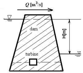
The primary parameters used in relations regarding hydro energetic potential are (Avram & Legendi, 2015):
flow, Q [m3/s] ––is the volume of water V that passes in time unit t through a particular reference section;
operation efficiency, ε ––defines the amount of energy actually produced in time unit at the turbine shaft or generator terminals;
water potential energy, E [J] – the water volume V located at H level above the reference level:
(1)
where: is the water density [kg/m3]; – gravitational acceleration [m/s2]; -water volume, [m3];
– difference between levels, [m].
IfQ =ct andH =ct, the absorbed power P has the expression: [kW] (2)
The main HPP scheme highlighting the hydropower potential (Figure
The turbine is intercalated in the energetic circuit and driven by the water flow Q. The rotary hydraulic engine (turbine) takes over the energy water volume passing through the reference section and converts it into mechanical power transmitted through the driving shaft.
The power at the turbine’s driving shaft takes into account the turbine energy conversion output,
[kW] (3)
The actual electrical power delivered to the electrical machine's terminals (electric generator) also takes into account the generator energy conversion output,
[kW] (4)
The installed power
The exploitation efficiency is quantified with the relationship:
[kWh] (5)
where:
The electric energy actually delivered to the NES,
Research Questions
Related to hydroelectrical power plants (HPP) general aspects this paper focuses a certain case in a view to study the technological flow of water energy conversion into the final electrical energy and the proper maintenance operations needed.
The topics that are to be debated.
The Voineşti hydro electrical power plant (HPP) is pursuedto be studied, with its main component elements and the specific maintenance aspects. The present material is looking to present the maintenance operations into phases corresponding to the related equipment in question.
Purpose of the Study
By information gathered in situ, the Voineşti HPP characteristics are presented and analysed. (Table
The Voineşti HPP main constructive and technological parameters.(Avram & Legendi, 2015)
A 5700 m length and 2,8 m diameter gallery leads Târgului River water that passes then to Lereşti HPP. The 15 m3/s water flow runs a 20 MW installed power Francis turbine.
At water drainage in Lereşti HPP, at a height of 720m, there is a 170000m3 water storage lake. From this polder, a 3650m adduction gallery leads the water to Voineşti HPP, following a surge chamber and a 75m forced pipe. The Voineşti HPP is equipped with a vertical Francis turbine having5,4MW installed power of and a 10,3m3/s flow at 68m difference level. The 6,5 MW generator is coupled to a 10MVA converter.
Research Methods
Surveying and mapping the Târgului river course in situ, the purposed topics are presented.
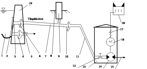
The Voineşti HPP scheme and its main component elements
1- Lereşti polder;2- grillage; 3- socket; 4-polder wash bowl; 5- polder wash pipe; 6- gallery valve adduction; 7- adduction gallery; 8-surge chamber layout deck; 9- surge chamber ; 10- surge chamber butterfly throttle; 11- pressure pipe-line; 12- turbine shut-off valve; 13- Voineşti HPP building; 14- Francis vertical turbine; 15- escape channel; 16- generator; 17- electric energy transporting to transformer; 18- connection to power grid through transformer station; 19- embankment]
The Voineşti HPP main components and their sequence in the technological scheme are presented above (Figure
Findings
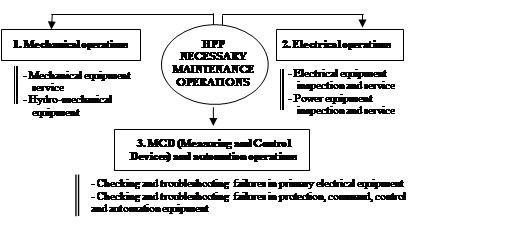
Maintenance represents the total maintenance and repairing operations of a technical system.In order to maintain and improve the HPP operating parameters and to increase the average running times, the following maintenance operations (Bucurescu, 2014) are performed on three main sections (figure

Mechanical operations.
-
Pre-mechanical repairs: functional check of valves and electro-hoists; establishing and locating leaks of water, air and oil; closure and blocking of the flat valve of Lereşti polder power plug in closed position; closing and mechanical locking butterfly valves; water drainage from the forced duct, spiral casing and exhauster cone; oil evacuation from hydro-aggregate bearings; revision of the exhaustion system for water infiltration; closing mechanical valves on the intake section in the cooling water pumps (Bardescu, 2014) .
-
Exciter: revision of the cardan joint and throttle bearings, bearing replacement; revision of the inspection windows from the brush collectors by filling the screws from the inspection screens; centring the exciter casing.
-
Radial-axial sliding bearing: cooling water circuit revision (pipe inspection, connectors and valves); cooling coat with internal sanding caps and restoration anti-corrosion protection, leak proof, check bolts, replace where necessary- the sealing paste will be used when refitting; check-up, eventual axial segments replacement, work surface preparation and insulation restoration.
-
Turbine bearing: repairing to eliminate turbine oil loss, replacement gaskets; interior cleaning and cleaning oil cooler turbine and oil transport pipes; check-up and inspection of the four-part turbine bearing; restoration of oil circulation pipes between the bath and the bearing cap (replacing the rubber hoses with pipe).
-
Turbine cover: turbine sealing system repair; labyrinth water exhaust system repair, replace the connections in the labyrinth water exhaust turbine cover; turbine cooling and lubrication repair, including filter review, with filter cell replacement.
-
Rotor generator lift-brake assembly: replacement/change sealing system for lifting and braking clutch; replacing the rotor braking system in a view to "automatic" drive.
-
Cooling water installation: overhaul cooling water filters, filter sieves replacement; water cooling water pump replacement; valves and throttle sense revision - repairing by original parts replacement, if applicable; electro-valve dismantling and restoring circuit; corrosion protection repair.
-
Fire-extinguishing system and basin GFS (guard fire safety): replacing screw-down valve float driven for water inlet from the forced duct into the fire basin; fire basin cleaning/clogging; overhaul/replacement key drawer valves fire basin installation; replacement of thermal insulation frost protection for pipes and fire basin armatures.
-
Voinesti water outlet: inspection of electromechanical equipment; corrosion protection installations repairing
-
Oil holding: manufacturing steel grading rules for measuring oil level in tanks and mounting nearby level optical indicators; gaskets and seals tank caps replacement, supply and fittings air filter caps with silica gel; corrosion protection repairing
-
Compressors: compressor overhaul: shift valve replacement.
-
Samples and checks: verification and correction of the general HA (hydro-aggregate)shaft line; hydraulic circuits pressurization; conducting samples with group installations, making adjustments, preparing the group for commissioning; rotor generator dynamic balancing; general cleaning, evacuation of TDVs (tools, devices, verifiers).
Electrical operations.
-
Stator works: generator stator dismantling and ride-on ride on Voinesti HPP mounting platform; upper and lower shield dismounting winding heads stator; stator winding and magnetic core expertise.
-
Rotor works: rotor generator disassembly after decoupling; weather protection by storing the rotor generator on the mounting platform; blowing rotor generator with air; cleaning and dyeing of magnetic core; cleaning, varnishing coil poles; poles mounting after verification; cable check and connections between excitatory and rotor generator; rotor fan blade cleaning, tightening verification and fan blade welding; inspecting insulating elements and replacing insulation bushings between rotor bindings and excitation bar, troubleshooting, varnishing; replacement of insulated bushings rotor bushings; check-up connections elastic connections winding damping.
-
Hydro-aggregate works: revision and repair of electromotive defects (disassembly, replacement of bearings, lubrication, re-assembly, functional tests); revision and repair of contactor defects (disassembly, rectification or replacement of used contacts, functional tests); overhaul and repair of circuit failures (fuses, heaters, cables, separators).
-
Power plant and lighting: replacement of lighting and force panels with slow burning fuses with panels provided with automatic switches; replacement of three-phase plugs.
-
General works: assurance and transportation to and from the workplace of the need for tools, devices and materials; preparing the formalities for starting and finishing the work.
MCD and automation operations.
- Visual inspection of all MCDs on functional status, visible defects detection; disassembly manometers, traffic signs dismantling; removing speed meters; manometer repairing, checking; checking and repairing electrical apparatus; temperature measuring apparatus, speed measuring devices, thermal resistance check-up and thermal resistance assembling in the stator winding; mounting manometers and calorimetric transducers; electrical apparatus installation; mounting temperature and speed meters; installation of thermo-resistances, laying and cable ties restoration; verifying connections in clamp strings, tiling, and replacing inappropriate clamps; commissioning tests (with signalling and triggering checks).
Conclusion
Some important conclusions are specified here bellow.
Potential advantages in using HPP.
The main advantages of using hydraulic energy are:
HPP have low operating costs and long service life compared to other types of power plants;
HPP are reliable, have high technical and economic performance level;
electricity can be produced at a constant rate through the HPP system;
dams are designed to be sustainable, thus generating electricity for many decades;
water lake can be used for drinking, industrial or irrigation water supply;
energy can be stored until the electricity production is disposed of;
HPP doesn’t produce greenhouse gases and doesn’t pollute the atmosphere (Bardescu & Legendi, 2014);
dams become landmarks through the landscapes they offer;
Voinesti HPP, due to the maintenance operations periodically and carefully tracked, is a safe and reliable unit that ensures the necessary energy source and water supply.
Negative aspects in using HPP and measures required.
The main disadvantages of hydraulic power exploitation are as follows:
loss of physical, chemical and biological qualities of the river on which on artificially intervenes for the HPP construction;
destruction of related habitats and ecological functions (decreases the river’s ability to self-purify);
negative effects on flora and fauna in the area;
most of the Romanian rivers are barred, captured or dyed, the beds of these courses being almost destroyed, with repercussions on the national fishing potential.
References
- Avram, P., & Legendi, A. (2015, August). The Râuşor hydropower planning. Thesis. Bucharest: UTCB.
- Anton I. & Tămaş M. (1992). Hydraulic Turbines and Turbotransmissions, vol. 1, Lithography of the Polytechnic University of Timişoara.
- Bardescu, I., & Legendi, A. (2014). Carbon dioxide-emission sources and decrasing solutions. Procedia - Social and Behavioral Sciences 180:1122-1128, https://dx.doi.org/ 10.1016/j.sbspro.2015.02.225
- Bucurescu, C. (2014). Reliability, maintenance and availability of technological equipment. Bucharest: Ed. Conspress
- Legendi, A., & Bardescu, I. (2010, November). Geothermal Power Units. EduWorld Conference, www.eduworld.ro
Copyright information

This work is licensed under a Creative Commons Attribution-NonCommercial-NoDerivatives 4.0 International License.
About this article
Publication Date
15 August 2019
Article Doi
eBook ISBN
978-1-80296-066-2
Publisher
Future Academy
Volume
67
Print ISBN (optional)
-
Edition Number
1st Edition
Pages
1-2235
Subjects
Educational strategies,teacher education, educational policy, organization of education, management of education, teacher training
Cite this article as:
Legendi*, A. (2019). Hydroelectrical Power Plant (Hpp) –Aspects Regarding The Operating And Maintenance Technologies. In E. Soare, & C. Langa (Eds.), Education Facing Contemporary World Issues, vol 67. European Proceedings of Social and Behavioural Sciences (pp. 1737-1745). Future Academy. https://doi.org/10.15405/epsbs.2019.08.03.213