
Modeling An Asynchronous Mode In Power Supply System


Abstract
Ensuring sustainability is one of the main tasks of the design and operation of electric power systems. Violation of the stability of parallel operation of generators and the appearance in the electric power system of a long asynchronous run can lead to a disruption in the power supply of a large number of electrical consumers and even to the complete collapse of the electric power systems. In this article consider the phenomenon of a two-frequency asynchronous mode is considered, as the most characteristic and often encountered in power systems. The analysis of the methods of registration and elimination of the asynchronous mode and the description of their principles of operation are carried out. The conditions for the occurrence of the asynchronous mode are studied and the analysis is performed for signs of the transition of the electrical network to asynchronous mode. On the basis of the RUSTab software package, an experiment was modelled that simulates the asynchronous mode and synchronous oscillations on the network section included in the IES of the East. The composition and parameters of the control action are determined, which allows eliminating the asynchronous mode without changing the network topology. The results obtained show the efficiency of application of asynchronous mode methods based on the constructed model.
Keywords: Synchronous oscillations, electrical swing center, asynchronous mode, modeling of power supply systems, automation of elimination of asynchronous mode
Introduction
Power supply systems are among the most complex man-made objects. In modern industrial life, power supply systems play a leading role for normal life support. The complex heterogeneous structure of power supply systems (Afanasyev, 2019) requires looking for new approaches to ensuring energy security and reliability.
Asynchronous running is the most severe mode after a short circuit, as it is accompanied by significant fluctuations in current and voltage, which can lead to equipment damage and loss of load stability. Asynchronous mode (AM) is usually considered on a two-machine system (Ivanov & Pastukhov, 2009), on which it is possible to simulate a two-frequency asynchronous operation (Figure 01).
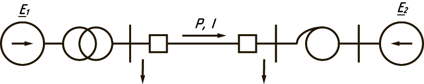
In the event of a violation of stability, the transfer of active power is stopped, and since the power of the turbines remains the same, the speed of rotation of the turbines and generators of one power plant (with a lower load) increases (generators are accelerated), and at another power plant (where there is a shortage of generating power) the speed of the turbines decreases.
The first characteristic feature of AM is a periodic change in the angle between asynchronous EMF from zero to 360° (Khrushchev et al., 2017).
Figure 02 shows a vector diagram of the EMF and power transmission voltages during the asynchronous run at a fixed time (in order to simplify the consideration of the EMF vector of the system and the generator, they are considered equal in modulus).
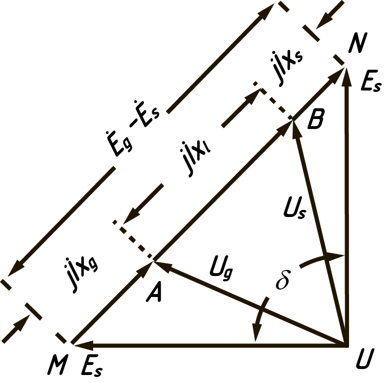
Each power transmission has a characteristic point at which the voltage at an angle of = 180o takes a minimum value or drops to zero. This point is called the electrical swing center (ESC).
Figure 03 illustrates the dependence of the voltage in the ESC and at the generator on .
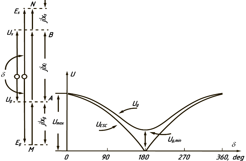
As the angle grows, the current through the electric power line increases, and at a value of the angle = 180o, the electric power transmission line turns on for a voltage twice rated. The magnitude of the current can cause both electrical and mechanical damage to the generators.
The moment of passage of the EMF vectors through the angle = 180o and the voltage distribution along the bond is shown in Figure 04.
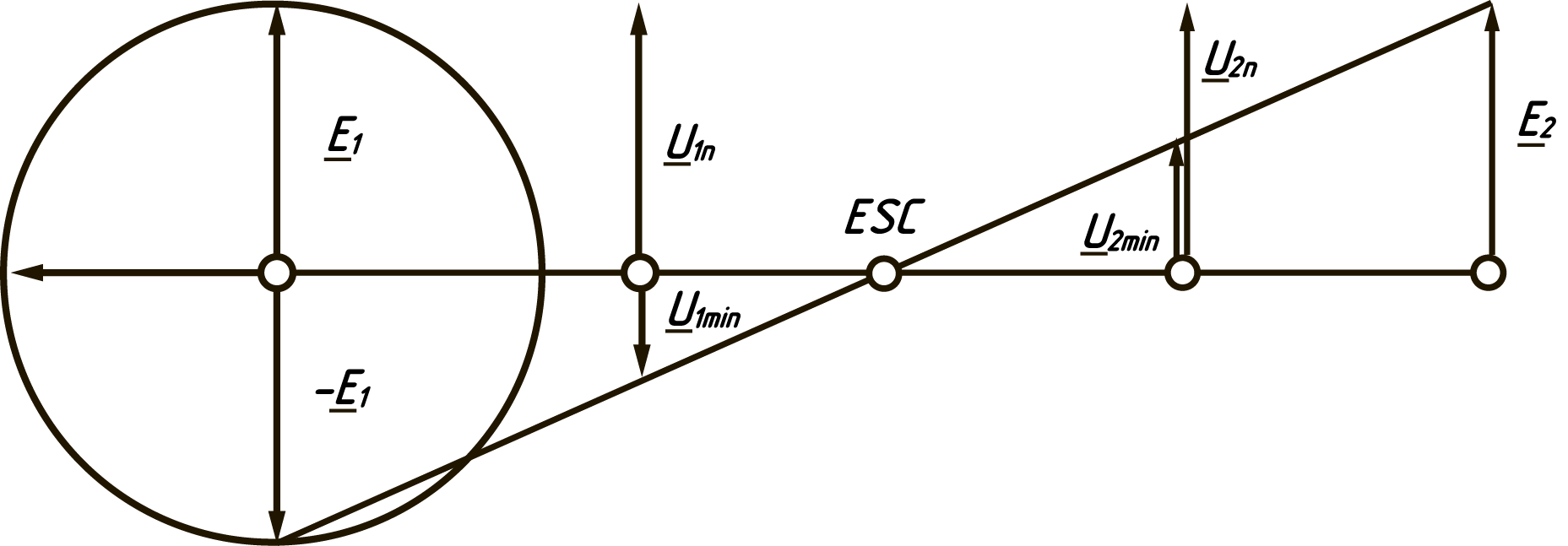
Figure 04 shows a planar projection of the voltage distribution at the moment of passing the angle of the 180 degree mark.
Note that at the points of power transmission, the voltages at AM have different values, to the left of the ESC, the voltage vector makes a full revolution with a slip frequency, and to the right it oscillates in magnitude and angle, and the swing increases as it approaches the ESC.
Physically, this means that the generators of power plants operate in the generator mode during the first half of the swing, and in the motor mode during the second half.
The average power for the swing period, transmitted through the power transmission, is zero (Jiaming, 2018).
The relationships for current and active power are illustrated in Figure 05.
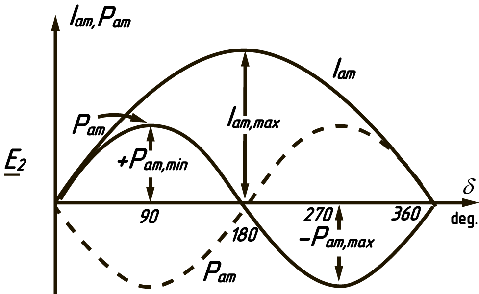
Thus, summarizing the above, we can note four signs of the asynchronous mode (McDonald, 2017), according to which the automatic elimination of the asynchronous mode (AEAM) detects the transition of the system to asynchronism:
1. Periodic change of angles between power plants;
2. Periodic change in the voltage swing along the system transit;
3. Periodic variation of the current swing in transit;
4. Periodic change in active power transmitted between power plants.
Problem Statement
Due to the complexity and multi-connectivity of modern electric power systems, the problem arises of effective control over the process of their normal functioning and prevention of emergency situations resulting from the occurrence of an asynchronous mode (Salam & Malik, 2018).
Research Questions
Determination of the conditions for synchronous oscillations and their transition to asynchronous mode at the section of the power supply system of the Far East.
Setting up and simulating the control actions necessary to eliminate emergency situations arising from the transition of the power supply system to asynchronous mode.
Purpose of the Study
Development of criteria allowing using parameters mode measured directly at the substation with installed control devices, determine in real time moments of opening and closing cycles of switches power lines to control asynchronous running on power system interconnection lines (Narovlyanskiy et al., 2010).
In the course of research on the topic under consideration, the following tasks were set:
- Clarification of the structure of indicators of quality and efficiency of AEAM;
- Identification of resources and ways to improve the efficiency of AEAM;
- Determination of generalized parameters of two-frequency asynchronous mode;
- Improvements in how to detect asynchronous mode;
- Creation of a mathematical model of a section of the power system for the analysis and forecast of the conditions for the occurrence of AM.
Research Methods
All existing AEAM devices are capable of detecting precisely the two-frequency asynchronous mode, discussed above, since it is based on the theory developed on a two-machine system.
The method for calculating the transient process used in the RUSTab software package allows simulating and analyzing the asynchronous mode with high accuracy, provided that the computational model is formed correctly (Sokolov & Gazizova, 2018). This makes it possible for the AR to jointly simulate the operation of devices for automatic elimination of the asynchronous mode - AEAM.
The computational model contains assumptions that do not allow simulating the exact response of real devices for detecting asynchronous mode:
The simulation is performed in root mean square values, thus, the harmonic composition of the analyzed quantities is not taken into account.
The three-phase system appears to be symmetrical, which excludes the analysis of unbalanced mode.
Modelling transition process
The computational model is based on a two-machine system.
For beginning, considered simulating a transient that starts with a synchronous swing and goes into asynchronous mode.
This experiment allows you to get an idea of the principles of operation and tuning of the AEAM model.
The study area contains Nizhne-Bureyskaya hydroelectric power station (NBHES) located in Amur Region and Primorskaya GRES (PRIM.GRES), located in the near Luchegorsk city. The intermediate node is substation TS 220 Birobidzhan.
The power of the generator in the NBHES unit is approximately three times greater than that of the unit. Prim.GRES. The load of Prim.GRES exceeds the generating capacity at this node.
Three power lines are involved in the scheme. Two parallel lines have the same parameters, the third line has about twice the resistance of the first two.
The AEAM device is located at Substation 220 Birobidzhan. Figure 06 shows steady state operation, excluding the operation of compensating devices providing a fixed voltage.
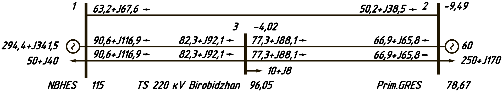
As a perturbation, the disconnection of two strong links with the balancing of the circuit for a weak link is modeled. Initially, to assess the parameters of the transient process, the ALAR devices are not involved and the transient process itself will develop only under the control of the speed regulators on the generators.
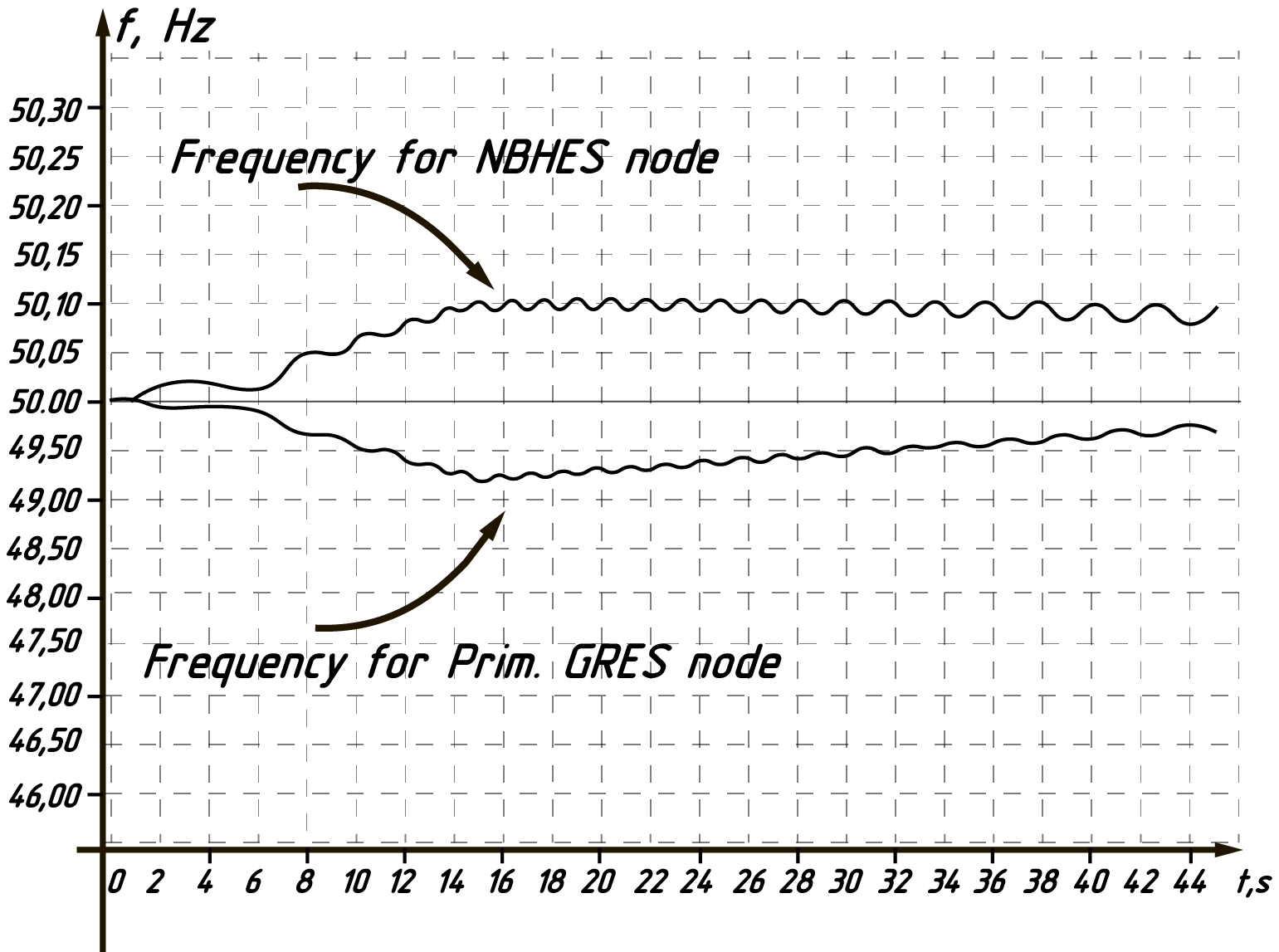
The graph of transient processes in frequency in the generating units is shown in Figure 07.
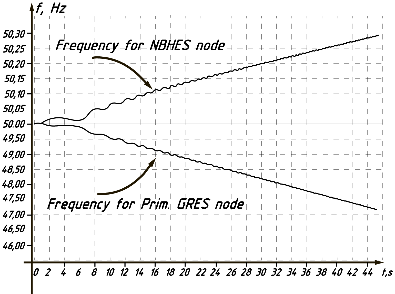
It can be seen from the graph that the frequency in a node with a generator of greater power increases, and in a node with a power deficit, it decreases accordingly.
The active and reactive power graph, see Figure 08, recorded at the intermediate node TS 220 Birobidzhan, gives an idea of the periodic change in power during synchronous swing and asynchronous run.
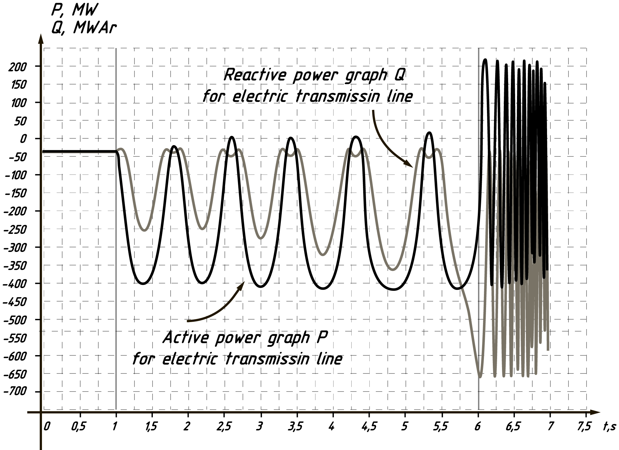
As you can see from the graph, the swing powers are so deep that they lead to a power reversal. After the sixth second, the swing switches to asynchronous mode with a sharp increase in frequency.
Simulation of AEAM-TS work
To detect asynchronous modes, AEAM-Ts have an angular detecting tool that predicts the occurrence of AM and triggers the device before the first asynchronous cranking (Ivanov & Pastukhov, 2009). This detecting device is used in cases where there is a real danger of a multi-frequency AM and when, during the first asynchronous rotation, deep voltage drops at substations located in the immediate vicinity of the electrical swing center are unacceptable
As a control action on the part of AEAM-Ts, shutdown of one generator unit per 100 MW at the NBHES node and disconnection of the load at the intermediate node TS 220 Birobidzhan are set.
Figure 09. illustrates the frequency graphs when simulating the operation of the AEAM-Ts.
It can be seen from the given graphs that the control actions launched the processes of the system exit from the asynchronous mode and further stabilization under the influence of the frequency and power control systems of generators.
Findings
Asynchronous modes of operation of power grids are rare. The consequences of asynchronous modes are associated with a high risk of damage to equipment and entail serious economic costs.
To effectively counter situations with the emergence of an asynchronous mode, it is necessary to comprehensively study the conditions for its occurrence, which is possible only with the help of simulation experiments (Scutariu & MacDonald, 2009; Zhang et al., 2016).
Since the carrying capacity of the line remaining in operation is insufficient to ensure the static stability of the power transmission, the AEAM Device formed a command to shutdown one of the NBHES generators. However, due to the limited amount of available control resource, static stability in the post-emergency mode was not ensured. This led to the further development of the accident, expressed in the occurrence of synchronous oscillations that grew into an asynchronous mode. At the same time, the hydraulic units of the NBHES that remained in operation began to rapidly increase the rotation speed.
During that time, while the emergency mode existed, the hydroelectric units of the NBHES accelerated, increasing their kinetic energy. The kinetic energy accumulated by the generators turned out to be so large, and the throughput of the power transmission line remaining in operation is so small that the mutual angle between the EMF of the generators and the system voltage began to rapidly increase and a transition to an asynchronous mode with a high slip frequency occurred.
Automation of the elimination of the asynchronous mode revealed the AM in the first cycle, when the mutual angle exceeded 180°. At the same time, the signal "Operation of the first stage" was generated, and also the signal "Braking" was correctly formed, which correctly indicated the nature of the violation of synchronous operation. However, the effect of the first stage on the formation of control actions was not envisaged, and the development of the AM continued. After that, the counting of complete asynchronous mode cycles began. Before the operation of the second stage, 5 complete AR cycles were performed, which corresponds to the given setpoint.
Based on the data from the registration of the emergency process, its important features are determined, which should be taken into account both in the preparation of requirements for AEAM devices and in their development.
An alternating active power flowed along the monitored line in the AM process: from minus 392 MW to plus 215 MW, that is, on each of the generators included in the operation, the active power varied from minus 2.2·Pnom to plus 1.6·Pnom.
The first transition through a mutual angle of 180° occurred after a relatively short time: 0.92 s passed from the moment of the emergency. At the same instant, the ALAR generated the signal «First stage actuation».
Completion of the full fifth AM cycle occurred in 5.865 s from the moment of the «accident» occurrence. At the same instant, the AEAM generated the signal «Second stage actuation».
The duration of the last, fifth, cycle was 2.2 s, which corresponds to a slip frequency of 0.455 Hz.
Conclusion
The paper considers the phenomenon of two-frequency asynchronous mode and its influence on the power system operation mode. On a test circuit simulating a section of a real power system, the conditions for the occurrence of synchronous oscillations with the further development of asynchronous operation are modeled.
Based on the results of the analysis of the considered «accident», the following conclusions can be drawn.
1. The resulting asynchronous mode has caused large alternating dynamic loads on the hydroelectric units of the NBHES, which is fraught with damage.
2. The refusal to form a control action from the ALAR-Ts on the signal "Operation of the first stage" led to an aggravation of the accident and an increase in its duration.
3. The ALAR-Ts device has shown its efficiency and, what is especially important, the ability to function correctly at large slips in asynchronous mode.
4. An effective method has been developed to identify the moment of occurrence of a two-frequency asynchronous mode in a section of the power system of the Far East.
5. The control actions necessary to eliminate the asynchronous mode without changing the network topology have been determined.
6. It has been shown experimentally that a violation of connectivity and stability in the power system can lead to an avalanche-hazardous increase in voltage and frequency in asynchronous mode
7. Criteria for the effectiveness and optimality of the use of emergency equipment were obtained
8. The influence of control actions on the part of emergency control devices on the stabilization of the network operation parameters is analyzed.
References
Afanasyev, A. P. (2019). Application Weighted Voronoi Diagrams to Determine the Areas of Responsibility of Transformer Substation, with Accounting Heterogeneity of Load Density, 2019 International Multi-Conference on Industrial Engineering and Modern Technologies (FarEastCon), 1-4.
Ivanov, K. M., & Pastukhov, V. S. (2009). Sposob effektivnogo viyavleniya momenta vozniknoveniya asinkhronnogo rezhima v energosisteme. [The Way of Effective Revealing the Moment of the Arising the Asynchronous Regime in Power System]. Nauchnye problemy transporta Sibiry i Dalnego Vostoka, 2, 382-384. [in Russ].
Jiaming, L. (2018). Measurement and Analysis of Overvoltages in Power Systems. John Wiley & Sons Singapore Pte Ltd.
Khrushchev, Yu. V., Kuleshova, Ye. O., & Shandarova, Ye. B. (2017). Elektromekhanicheskiye perekhodnyye protsessy v elektroenergeticheskikh sistemakh [Electromechanical transients in electrical power systems]. Tomsk: Izd-vo TPU [in Russ].
McDonald, J. D. (2017). Electric Power Substation Engineering. CRC Press Taylor & Francis Group.
Narovlyanskiy, V. G., Vaganov, A. B., & Ivanov, I. A. (2010). Rezul'taty ispytaniy ustroystva likvidatsii asinkhronnogo rezhima ALAR-M na elektrodinamicheskoy modeli energosistemy [Results of testing the device for eliminating the asynchronous mode ALAR-M on the electrodynamic model of the power system]. Releynaya zashchita i avtomatizatsiya, 1(01), 16-20 [in Russ].
Salam, A. A., & Malik, O. P. (2018). Electric Distribution Systems. John Wiley & Sons.
Scutariu, M., & MacDonald, M. (2009). Industrial power system protection against transmission system blackouts, 44th International Universities Power Engineering Conference (UPEC 2009), 1-5, 201-206.
Sokolov, A. P., & Gazizova, O. V. (2018). Improving the Accuracy Mathematical Modeling of Transients Emergency Mode Industrial Facilities Distributed Generation, 2018 International Youth Scientific and Technical Conference Relay Protection and Automation (RPA), 1-15,
Zhang, C., Li, Y., Yu, Z., & Tian, F. (2016). Feature selection of power system transient stability assessment based on random forest and recursive feature elimination, 2016 IEEE PES Asia-Pacific Power and Energy Engineering Conference (APPEEC), 1264-1268, https://doi.org/10.1109/APPEEC.2016.7779696
Copyright information

This work is licensed under a Creative Commons Attribution-NonCommercial-NoDerivatives 4.0 International License.
About this article
Publication Date
21 June 2021
Article Doi
eBook ISBN
978-1-80296-110-2
Publisher
European Publisher
Volume
111
Print ISBN (optional)
-
Edition Number
1st Edition
Pages
1-1168
Subjects
Social sciences, education and psychology, technology and education, economics and law, interdisciplinary sciences
Cite this article as:
Afanasyev, A. P. (2021). Modeling An Asynchronous Mode In Power Supply System. In N. G. Bogachenko (Ed.), Amurcon 2020: International Scientific Conference, vol 111. European Proceedings of Social and Behavioural Sciences (pp. 34-43). European Publisher. https://doi.org/10.15405/epsbs.2021.06.03.5