
Electrospun Poly (Ionic Liquid) Membrane Based Solar Cell For Sustainable Clean Energy


Abstract
The quest for sustainable and clean energy production has incentivized the development of solar cell technology. Dye-sensitized solar cells (DSSCs) have a significant influence on this revolution. Efficient and stable electrolyte systems are necessary for the outdoor application of DSSCs. An innovative polymeric ionic liquid (PIL), poly 3-decyl-vinyl imidazolium methyl methacrylate tetrafluoroborate was synthesized, characterized and blended with poly (ethylene oxide) (PEO). The polymer fibrous membranes have been fabricated by electrospinning technique, which were used as the electrolyte for DSSCs. Electrospun nanofibrous membrane possess high porosity and excellent specific surface area that can imbibe large amount of liquid electrolyte into its interconnected network structure. These membranes were studied by scanning electron microscopy (SEM), Fourier transform infrared spectroscopy (FT-IR), X-ray diffraction (XRD), differential scanning calorimetry (DSC) techniques and investigated their physical characteristics such as porosity, electron uptake and ionic conductivity. Photovoltaic and electrochemical effects have been examined. PEO/PIL membrane was compared with PEO for their efficiency. From the result, it was seen that PEO/PIL membrane exhibited superior power conversion efficiency (η), excellent ionic conductivity and better long term stability compared to cell with liquid electrolyte and PEO membrane. This novel PEO/PIL membrane based electrolyte in DSSC showed promising potential for the production of clean energy.
Keywords: Clean energydye sensitized solar cellpoly (ionic liquid)electrolyteelectrospun membranepoly (ethylene oxide)
Introduction
Solar energy
The yearly raise in global energy consumption will effect in increase of demands towards natural resources such as coal, petroleum and natural gas. These natural resources will take thousands of years to form and it cannot be replaced as fast as they are being consumed. These traditional fossil based fuel usages caused environmental problems such as carbon dioxide emission and irreversible climate changes (Luis et al., 2019). Among the energy sources existing, solar energy can fulfill the world’s ever growing energy needs (Muthuraaman et al., 2017). Photovoltaic cells directly convert solar energy to electricity.
Dye-sensitized solar cell (DSSC)
Among the photovoltaic cells, dye-sensitized solar cell (DSSC) has received widespread attention owing to their advantages such as simple fabrication, ecofriendly nature and remarkable energy conversion, which mimics some of the key processes in the natural photosynthesis during the operation (Ishanie et al., 2014). In general, DSSCs are composed of three parts: TiO2 photo anode, a counter electrode and an electrolyte.
Electrolyte
The electrolyte can be considered as central among the DSSC components, since it takes the main function as a medium for charge transport (Buraidah et al., 2017).
Basic requirements of the electrolytes used for DSSCs are:
The electrolyte must transport the charge carriers between electrodes with high redox potential.
The electrolyte must guarantee high ionic conductivity and make good contact with the electrodes.
The electrolyte must contain very good long term stability.
Highly efficient DSSCs usually utilize liquid electrolyte, but liquid electrolytes are prone to leak and evaporate making them unstable for outdoor application. Thus, quasi-solid state (QSS) electrolytes have been favoured owing to their considerably excellent conductivity, strong interfacial contact and high penetrative ability into the semiconductor (Yi-Feng et al., 2016). Electrospun polymer nanofibrous membranes in the form of QSS electrolyte caught a lot of attention due to their high porosity and their capacity to entrap large amount of liquid electrolyte and possessed an extremely high specific surface area (Mini & Sheeja, 2019).
Poly (ionic liquid) (PIL)
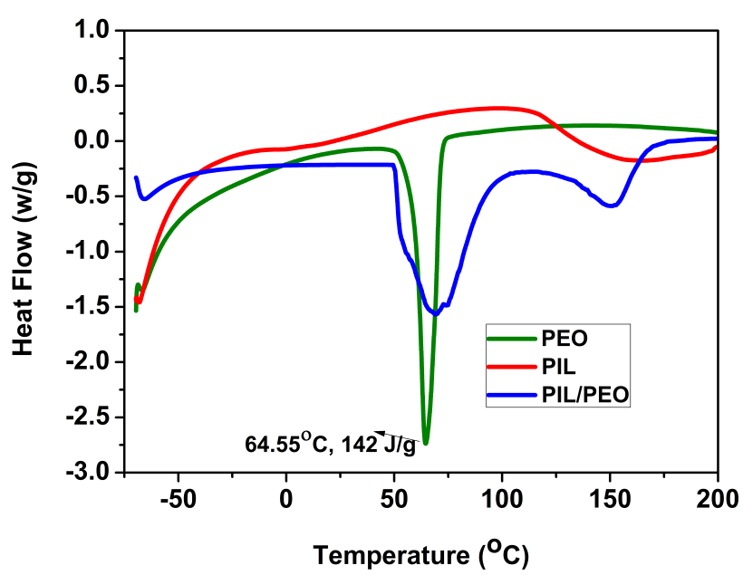
Recently, imidazolium based poly (ionic liquid) (PIL) electrolytes in DSSCs have received a lot of attention; due to their ability to show multiple functions upon tuning their molecular structure and also provide excellent long-term stability and power conversion efficiency (Xiaojian et al., 2012). The non-volatile imidazolium cations stop the unfavorable recombination reactions by blocking the possible sites for electron leakage on the TiO2 surface and thereby enhance the performance of DSSCs (Hao-Wei et al., 2018). It also increases the ionic conductivity of polymer matrix through charge transport network formation via - stacking of imidazole segment (Silvia et al., 2017). The oxygen atom present in the methyl methacrylate (MM) forms a co-ordination bond with the Li atom and improves the ionic conductivity of the electrolyte. As the PIL could not be electrospun due to their lower molecular weight, the synthesized PIL was blended with a polymer possessing high molecular weight to obtain nanofibrous membrane. Poly (ethylene oxide) (PEO) was selected as the blending polymer due to its high chemical stability and better ion transport due to the consolidation of their cation-complexation capability (Yanyan et al., 2015; Zebardastan et al., 2017). Blending with PIL can solve the problem of PEO crystallization that occurs below 60°C.
Problem Statement
Leakage and solvent evaporation of the liquid electrolyte diminishes the stability and efficiency of DSSCs, thus making them unfit for outdoor applications (Yi-Feng et al., 2016). The use of solid state material based electrolyte shows better stability and low efficiency due to their poor interfacial contact between the electrodes (Shanmuganathan et al., 2016). In recent years, many attempts have been made to improve performance of DSSCs by using electrospun based quasi-solid electrolytes. Authors have fabricated PIL based electrospun membrane (Hao-Wei et al., 2018) which exhibited power conversion efficiency of 9.26% and provided long term stability (i.e. 97% of initial cell efficiency) compared with the liquid electrolyte. The decreased cell efficiency for the cell with the liquid electrolyte was related to the predictable leakage of the liquid electrolyte and evaporation of the volatile organic solvent.
Research Questions
-
How quasi-solid state electrolyte aid in enhancing the stability and efficiency of DSSCs?
-
What is the significance of electrospun nanofibrous membrane morphology in the stability of DSSCs?
-
Does the poly (ionic liquid) architecture affect the efficiency and stability of DSSCs?
Purpose of the Study
-
To synthesise poly (ionic liquid) (PIL) viz., 3-decyl-vinyl imidazolium methyl methacrylate tetrafluoroborate through free radical polymerization to increase the efficiency of DSSCs.
-
To incorporate the prepared PIL into poly (ethylene oxide) and fabricate them into nanofibrous membrane via electrospinning technique for the higher uptake of liquid electrolyte.
-
To study the physical and electrochemical characterizations of the prepared membranes.
-
To fabricate DSSCs with electrospun membranes and their photovoltaic performances and stability are to be studied and compared with the liquid electrolyte containing DSSCs.
Research Methods
Materials
Poly (ethylene oxide ) (PEO) (average Mw = 200,000g/mol), iodine (I2), lithium iodide (LiI), 4-tert-butylpyridine (TBP), Chloroform, Vinyl imidazole, Sodium tetrafluroborate, Azobisisobutyronitrile (AIBN) and absolute ethanol were purchased from Sigma-Aldrich Co., Ltd. Methyl methacrylate and dichloromethane (DCM) were purchased from SRL Chemicals Pvt. Ltd., India. Nanocrystalline TiO2 (nc-TiO2) paste coated on FTO conducting glass (15Ω/sq), cis-Diisothiocyanato-bis (2,20-bypyridyl-4,40-dicarboxylato) ruthenium(II) bis (tetrabutylammonium) (N719 dye) and Pt counter electrode were purchased from Greatcell Solar's DSL, Australia.
Preparation of electrospun polymer nanofibers
PEO solution (A) with a concentration of 11 w/v % was prepared in chloroform at room temperature. Solution (B) was prepared by adding 0.55 g of PIL in solution (A). The prepared polymer solution was loaded into a 5 mL syringe attached to a stainless steel needle with a diameter of 0.3 mm. The flow rate of the solution was adjusted to 3 mL/h with the help of a syringe pump. An aluminum foil was placed as a collector at a distance of 15 cm from the needle and a high voltage of 30 kV was applied at the end of the needle. The electrospinning parameters were set after optimization.
Fabrication of DSSC devices
The TiO2 photo electrode was fabricated by immersing the annealed screen printed nc-TiO2 into 0.5mM of N719 dye in absolute ethanol for 24 h at room temperature under dark conditions followed by rinsing with anhydrous ethanol and air dried. A gasket frame (MSOO4610-10) with an optimal thickness of 60 m was inserted between the dye-adsorbed nc-TiO2 electrode and Pt counter electrode and the cell was pressed together using clips. The gasket thickness was sufficient to allow for the addition of a sufficient amount of electrolyte. Quasi-solid state DSSCs was assembled using electrospun nanofibrous membrane of definite dimension being sandwiched between the dye imbibed TiO2 working electrode and the Pt counter electrode (Marwa et al., 2016; Tan et al., 2019) and clipped tightly. A drop of the prepared electrolyte solution containing 0.05 M iodine, 0.1 M lithium iodide, 0.6 M of PMII, and 0.5 M of TBP in 1 mL of a mixture of valeronitrile (15%) and acetonitrile (85%) were then introduced into the clamped electrodes. The active area of the DSSC was found to be 0.49 cm2. For comparative studies, another DSSC was fabricated using liquid electrolyte without electrospun nanofibers.
Findings
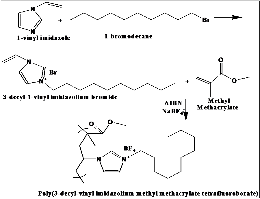
Synthesis of poly (ionic liquid)
Poly (ionic liquid) (PIL), 3-decyl-vinyl imidazolium methyl methacrylate tetrafluoroborate was synthesized via a simple procedure, as shown in Figure
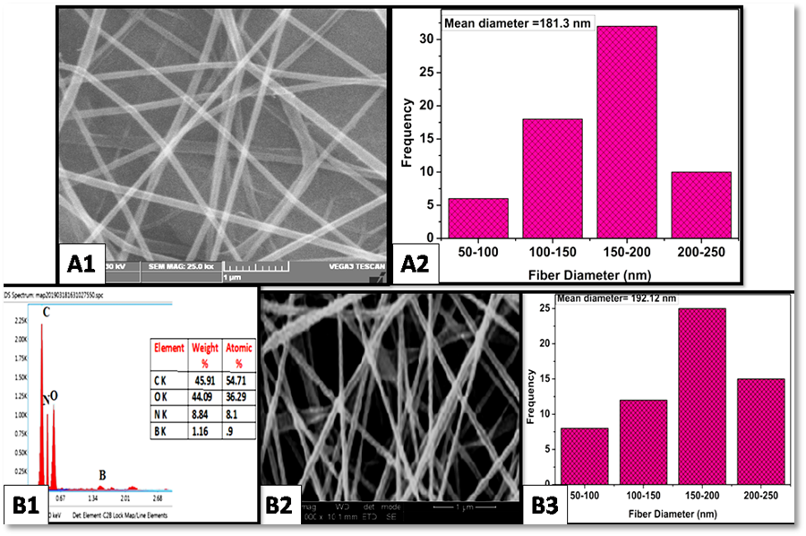
Study of the morphology
Figure
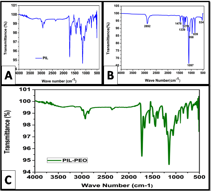
FTIR study
Figure
The peaks at 2850 cm-1 and 1390 cm-1 indicate the presence of C-H stretching and C-H bending vibrations respectively. The FT-IR spectrum of PEO nanofibers in Figure
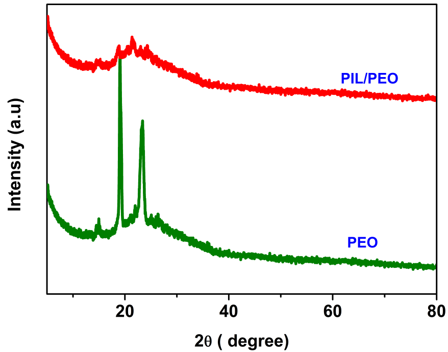
XRD analysis
Figure
(1)
Differential scanning calorimetric studies
Figure
Electrolyte uptake (U), porosity (P) and Ionic Conductivity (σ)
The porosity (P) of the nanofibrous membrane was determined by immersing the electrospun membrane into n-butanol for 1 h. The weights of the nanofibrous membranes before (mi) and after (ma) immersion were measured. The densities of n-butanol and the sample were represented as ‘b’ and‘s’ respectively. Porosity was evaluated by using the equation (2) (Mini & Sheeja, 2019).
(2)
The equation (3) (Mini & Sheeja, 2019) was used to measure liquid electrolyte uptake in the electrospun membranes, where ‘mo’ and ‘m’ are the weight of the nanofibrous membrane before and after imbibing the liquid electrolyte.
(3)
The ionic conductivity () of the membranes was obtained using equation (4) (Karuppanan et al., 2015).
Where, ‘
(4)
Ionic conductivity of PIL/PEO nanofibrous membrane based electrolyte was observed to have a higher value than that of the unblended PEO nanofibers. The reason could be due to the amorphous nature of the blend that could imbibe more liquid electrolyte into the pores. The charge carrier mobility enhanced due to an increase in amorphous nature. All the prepared polymer membranes exhibited good porosity due to their three dimensional network architecture (as shown in Table
Photovoltaic Performances of DSSC
The electron transfer mechanism (Malaisamy et al., 2014) taking place in DSSCs containing PIL/PEO electrolyte are shown below:
N719 dye (D) absorbs photons and produces excited electron (D*)
D/TiO2 +hD*/ TiO2
The excited electron in the dye goes to the conduction band of TiO2, to form the oxidized dye (D+), and the electron diffuses through TiO2 coated anode and moves through the external load and reaches the Pt counter electrode.
D*/ TiO2D+/ TiO2 + e- / TiO2
The oxidized dye (D+) was regenerated by accepting electrons from reduced state I- to produce the oxidized state I3- of the electrolyte
D+/ TiO2 + I-(re)D/TiO2 + I3- (ox)
Oxidized form of I3- migrates to cathode through polymer electrolyte, and gets reduced to I- by accepting electron from the Pt counter electrode (Pt CE).
I3- (ox) + e-/Pt CE I- (re)
Thus, DSSCs produce current from solar light without any chemical transformation. Iodine forms charge-transfer complex with the lone pair of electrons of nitrogen (N) atom in the imidazolium based PIL which prevents the recombination of triiodide present in the electrolyte and thereby inject electrons which increases the iodide concentration of the polymer electrolyte. Interconnected PIL/PEO electrospun nanofibrous membrane helps to entrap large amount of liquid electrolyte and thereby increase the stability of DSSCs.
Photovoltaic performance of the DSSCs were measured using LOT Technologies solar simulator equipped with a 150 W xenon under air mass 1.5 and 100 mW cm-2 of light intensity.
Photovoltaic parameters, light-to-current conversion efficiency (η) and Fill Factor (FF) were calculated by using equation (5) and (6) as shown below (Khushboo et al., 2018).
(5)
(6)
Where, ‘
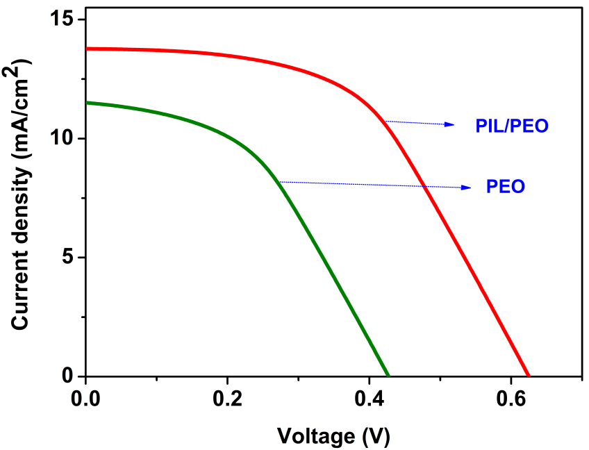
The overall power conversion efficiency of electrospun PEO was found to be lower than that of the PIL/PEO blend nanofibers as shown in Figure
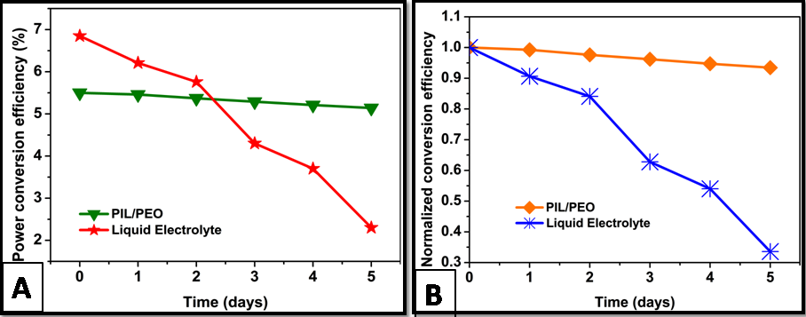
Stability measurement
In Figure
Conclusion
The liquid electrolyte used in DSSC was found to be highly unstable. The present work is therefore aimed to increase the stability of the liquid electrolyte using a quasi-solid state electrolyte. To achieve this objective, poly (3-decyl-vinyl imidazolium methyl methacrylate tetrafluoroborate) (PIL) was synthesized, characterized and fabricated as electrospun membrane by blending with PEO and employed as an electrolyte for the fabrication of QSS-DSSC. The resultant PIL/PEO membrane based DSSC showed efficiency of 5.34% under the simulated solar spectrum illumination (100 mW cm-2), which was higher than that of the PEO membrane based electrolyte. The electrospun nanofibrous membrane entrapped the liquid electrolyte in its three dimensional network structure, reduced leakage and evaporation of liquid electrolyte and thus enhanced the stability. The limitation of the prepared PIL/PEO membrane compared to liquid electrolyte was that it showed lower photo conversion efficiency due to low ionic conductivity. This is because the polymer matrix hindered the ionic mobility between electrodes. The prepared PIL/PEO membrane based electrolyte exhibited better stability (93.4% of its initial cell efficiency after 5 days) than the liquid electrolyte and thus showed good potential for future outdoor applications. The future work aims to increase ionic conductivity of the membrane and improve their conversion efficiency.
Acknowledgments
The authors gratefully acknowledge the instrumentation facility provided under FIST-DST and DRS-UGC to the Department of Chemistry, Anna University, Chennai. The instrumentation facility offered by the Department of Chemistry, IIT Madras is also gratefully acknowledged.
References
- Azli, A. A., Manan, N. S. A., & Kadir, M. F. Z. (2015). Conductivity and dielectric studies of lithium trifluoromethanesulfonate doped polyethylene oxide-graphene oxide blend based electrolytes. Advances in Materials Science and Engineering, https://doi.org/10.1155/2015/145735
- Buraidah, M. H., Shahan, S., Teo, L. P., Faisal, I. C., Careem, M. A., Albinsson, I., Mellander, B. E., & Arof, A. K. (2017). High efficient dye sensitized solar cells using phthaloylchitosan based gel polymer electrolytes. Electrochimica Acta, 245, 846–853. https://doi.org/10.1016/j.electacta.2017.06.011
- Chang, M., Erchuang, C., Junjing, L., Qingchao, F., Liqiang, W., Yan, S., & Jingli, S. (2018). Synthesis of mesoporous ribbon-shaped graphitic carbon nanofibers with superior performance as efficient supercapacitor electrodes. Electrochemica Acta, 292, 364-373. https://doi.org/10.1016/j.electacta.2018.07.135
- Deyab, M. A., Zaky, M. T., & Nessin, M. I. (2017). Inhibition of acid corrosion of carbon steel using for imidazolium tetrafluroborate ionic liquids. Journal of Molecular Liquids, 229, 396-404. https://doi.org/10.1016/j.molliq.2016.12.092
- Elashmawi, I. S., & Gaabour, L. H. (2015). Raman, morphology and electrical behavior of nanocomposites based on PEO/PVDF with multi-walled carbon nanotubes. Results in Physics, 5, 105–110. https://doi.org/10.1016/j.rinp.2015.04.005
- Hao-Wei, P., Hsin-Fu, Y., Yi-June, H., Chun-Ting, L., & Kuo-Chuan, H. (2018). Electrospun membranes of imidazole-grafted PVDF-HFP polymeric ionic liquids for highly efficient quasi-solid-state dye-sensitized solar cells. Journal of Materials Chemistry A, 6, 14215-14223. https://doi.org/10.1039/C8TA01215F
- Ishanie, R. P., Akhil, G., Wanchun, X., Torben, D., Udo, B., Richard, A. E., Andre´Ohlina, C., & Leone, S. (2014). Introducing manganese complexes as redox mediators for dye-sensitized solar cells. Physical Chemistry Chemical Physics, 16, 12021-12028. https://doi.org/10.1039/C3CP54894E
- Karuppanan, P., Smita, M., & Sanjay, K. N. (2015). Chemically exfoliated nanosilicate platelet hybridized polymer electrolytes for solid state dye sensitized solar cells. New Journal of Chemistry, 39, 8602-8613. https://doi.org/10.1039/C5NJ00795J
- Khushboo, S., Vinay, S., & Sharma, S. S. (2018). Dye-sensitized solar cells: fundamentals and current Status. Nanoscale Research Letters, 13, 381-387. https://doi.org/10.1186/s11671-018-2760-6
- Luis, H., Sara, G., & Víctor, A. (2019). A review of photovoltaic systems: Design, operation and maintenance. Solar Energy, 188, 426-440. https://doi.org/10.1016/j.solener.2019.06.017
- Malaisamy, S., Subbiah, R., & Paramasivam, M. (2014). Preparation of PVDF-PAN-V2O5 hybrid composite membrane by electrospinning and fabrication of dye-sensitized solar cells. International Journal of Electrochemical Science, 9, 3166-3180.
- Marwa, F., Jehan, E. N., Mamoun, M., Shaker, E., Moataz, B. S., & Abd, El-Hady, B. K. (2016). Quasi-solid-state electrolyte for dye sensitized solar cells based on nanofiber PMA-PVDF and PMA-PVDF / PEG membranes. International Journal of Electrochemical Science, 11, 6064 – 6077. https://doi.org/10.20964/2016.07.19
- Mini, T., & Sheeja, R. (2019). Dye-sensitized solar cells based on an electrospun polymer nanocomposite membrane as electrolyte. New Journal of Chemistry, 43, 4444-4454. https://doi.org/10.1039/C8NJ05505J
- Muthuraaman, B., Viswanathan, E., Jiajia, G., & Lars, K. (2017). Polymer-doped molten salt mixtures as a new concept for electrolyte systems in dye-sensitized solar cells. ACS Omega, 2, 6570−6575. https://doi.org/10.1021/acsomega.7b00925
- Roger, J., Assaf, A., Piers, R. F. B., Li, X., Chunhung, L., & Brian, C. O. (2014). 2000 hours photostability testing of dye sensitised solar cells using a cobalt bipyridine electrolyte. Journal of Materials Chemistry A, 2, 4751-4757. https://doi.org/10.1039/C4TA00402G
- Shanmuganathan, V., I-Ping, L., Li-Tung, C., Yi-Chen, H., Chiao-Wei, L., & Yuh-Lang, L. (2016). Effects of TiO2 and TiC nanofillers on the performance of dye sensitized solar cells based on the polymer gel electrolyte of a cobalt redox system. ACS Applied Materials & Interfaces, 8, 24559−24566. https://doi.org/10.1021/acsami.6b06429
- Silvia, M., Gabriel, A., Ra´ul, P., Jairton, D., Mar´ıa, I. B., Eduardo, G., & Santiago, V. L. J. (2017). Hierarchically structured polymeric ionic liquids and polyvinylpyrrolidone mat-fibers fabricated by electrospinning. Journal of Materials Chemistry A, 5, 9733–9744. https://doi.org/10.1039/C7TA02447A
- Tan, C. Y., Omar, F. S., Norshahirah, M., Saidi, F. N. K., Ramesh, S., & Ramesh, K. (2019). Optimization of poly(vinyl alcohol-co-ethylene)-based gel polymer electrolyte containing nickel phosphate nanoparticles for dye-sensitized solar cell application. Solar Energy, 178, 231–240. https://doi.org/10.1016/j.solener.2018.12.043
- Venkateswararao, A., Justin, T. K. R., Chuan-Pei, L., Chun-Ting, L., & Kuo-Chuan, H. (2014). Organic dyes containing carbazole as donor and π linker: optical, electrochemical, and photovoltaic properties. ACS Applied Materials & Interfaces, 6, 2528−2539. https://doi.org/10.1021/am404948w
- Xiaojian, C., Jie, Z., Jinyu, Z., Lihua, Q., Dan, X., Haigang, Z., Xiaoyuan, H., Baoquan, S., Gaohui, F., Ye, Z., & Feng, Y. J. (2012). Bis-imidazolium based poly (ionic liquid) electrolytes for quasi-solid-state dye-sensitized solar cells. Journal of Materials Chemistry, 22, 18018–18024. https://doi.org/10.1039/C2JM33273F
- Yanyan, D., Qunwei, T., Yuran, C., Zhiyuan, Z., Yang, L., Mengjin, H., Peizhi, Y., Benlin, H., & Liangmin, Y. (2015). Solid-state dye-sensitized solar cells from poly(ethylene oxide)/polyaniline electrolytes with catalytic and hole-transporting characteristics. Journal of Materials Chemistry A, 3, 5368-5374. https://doi.org/10.1039/C4TA06393G
- Yi-Feng, L., Chun-Ting, L., Chuan-Pei, L., Yow-An, L., Yamuna, E. R., Vittal, Ming-Chou, C., Jiang-Jen, L., & Kuo-Chuan, H. (2016). Multifunctional iodide-free polymeric ionic liquid for quasi-solid- state dye-sensitized solar cells with a high open-circuit voltage. ACS Applied Materials & Interfaces, 8, 15267−15278. https://doi.org/10.1021/acsami.6b02767
- Zebardastan, N., Ramesh, S., & Ramesh, K. (2017). Performance enhancement of poly (vinylidene fluoride-co-hexafluoro propylene)/polyethylene oxide based nanocomposite polymer electrolyte with ZnO nanofiller for dye-sensitized solar cell. Organic Electronics, 49, 292-299. https://doi.org/10.1016/j.orgel.2017.06.062
Copyright information

This work is licensed under a Creative Commons Attribution-NonCommercial-NoDerivatives 4.0 International License.
About this article
Publication Date
12 October 2020
Article Doi
eBook ISBN
978-1-80296-088-4
Publisher
European Publisher
Volume
89
Print ISBN (optional)
-
Edition Number
1st Edition
Pages
1-796
Subjects
Business, innovation, sustainability, environment, green business, environmental issues, urban planning, municipal planning, disasters, social impact of disasters
Cite this article as:
Thomas, M., & Rajiv, S. (2020). Electrospun Poly (Ionic Liquid) Membrane Based Solar Cell For Sustainable Clean Energy. In N. Samat, J. Sulong, M. Pourya Asl, P. Keikhosrokiani, Y. Azam, & S. T. K. Leng (Eds.), Innovation and Transformation in Humanities for a Sustainable Tomorrow, vol 89. European Proceedings of Social and Behavioural Sciences (pp. 218-231). European Publisher. https://doi.org/10.15405/epsbs.2020.10.02.21