
SO2 In Flue Gas Desulphurization For Different Types Of Sub-Bituminous Coal

Abstract
The energy landscape transform globally including Malaysia. Thermal coal fired power plants are the backbone of the power generation industry in Malaysia in ensuring sustainable electricity power supply to the national grid system to cater for the ever growing demands of a developing country. By comparing with others fuel as distillate in power generation sectors; natural gas and medium oil, coal is the best prefer due to lower price market. As reported in Malaysia Energy Outlook, several new coal power plants coming into the system in the next 5 years, gas consumption is expected to decrease roughly by about 12 percent in 10 years’ time. On the other hand, being the base load fuel in the generation mix due to price advantage, coal consumption is expected to increase to more than 30 million tonnes per annum. In the medium term, coal is expected to maintain its position as the most used fossil fuels in the electricity generation. However, one of the major downside of combusting coal to produce electricity is that the flue gases (exhaust gases) produced has high concentration of contaminants such as SO2 and NOx, which has various negative impacts on the environment. The Flue Gas Desulphurization (FGD) plant is designed to remove SO2 from the flue gas, which is a bypass of combusting coal. This study analyses the effective SO2 reduction achieved by the FGD system. Several types of sub bituminous coal with different specification are used for combustion in the boiler. The results of this study clearly shows that the different types of sub bituminous coal lead to varying percentage of SO2 removal. Besides, the study shows the relative correlation between sub bituminous SO2 content and the SO2 emission at the stack.
Keywords: Thermal Power PlantSub-bituminous CoalSulphur DioxideFlue Gas Desulphurization (FGD)
Introduction
Response to the economic constrain, coal was selected as the main fuel for the thermal power plant in generating the electricity. Cost and price of the coal become the main factors in the selection compared to the others fuel type; oil and gas. However, combustion product of coal contributes to the largest source of CO and SO2 to the global. Consequently, the phenomena affect to the emission of greenhouse gases and anticipated change in the climate. Indeed, the selection to the types of coal is critically important due to different characteristic between coal rank; high volatile bituminous coal, bituminous coal, sub bituminous coal, and lignite coal. Besides, the amount of fixed carbon content in coal and the amount of volatile matter in coal determine the coal ranking in various types of coal. In addition, the high rank coal also presents the coal with low moisture percentage and the coal with high ash content.
The coal characteristic is measure through ultimate analysis and approximate analysis. The sulphur contents were measuring follow the ASTM D4239, ISO 351, AS1038.6 and British Standards (BS). It is important to measure the sulphur content in coal samples to evaluate the potential sulphur emissions from coal combustion, or for contract specifications purposes. As described before, proximate analysis method measures the coal characteristic such as percentage of sulphur contents, moisture content, weighted of percentage for volatile matter, amount of ash percentage, and fixed carbon content. Meanwhile, for chemical composition in coal, the ultimate analysis method applied, which is more comprehensive. The ultimate analysis measuring the chemical content such as carbon, hydrogen, sulphur, oxygen, and nitrogen which are present in coal. From the ultimate analysis, the analysis is presenting in percentage of the total mass of the original coal from the coal yard.
According to United State and Canada, sub bituminous coal is rank between lignite and bituminous coal, firmly coal in dark brown colour. According to Spitz et al. ( 2008), the sub-bituminous coal contains with high moisture and high volatile matter which is more reactive in combustion compare to the bituminous coal types. However, this sub-bituminous coal present lower sulphur contents as below as 2 percent by weight in coal. As non-coking coal and less sulphur contents, sub-bituminous coal has 10 to 45 percent of volatile matter with more moisture compared to bituminous coal types. The carbon content for sub-bituminous coal is between 35 to 45 percent with ash content about 10 percent and below. Approximately is about 0.5 to 2.0 of nitrogen content from the coal weight and is about 2 to 5 percent of hydrogen content from the coal weight. In addition, the sub-bituminous coal was found near the ground surface and not involves with high cost. Relatively, it’s easy to get the coal but high risk in managing the coal during mining activities. From the ultimate analysis results, its conclude the sub-bituminous coal easily drive to emission hazard which consist with particulate matter (PM), sulphur oxides (SOx), nitrogen oxides (NOx), and mercury (Hg). In-term of combustion purpose, the sub-bituminous coal can burn in the boiler, but the combustion product must be managing properly ( Nuraini, Salmi, & Aziz, 2018).
The main by-products of combusting coal are the flue gas. In a coal fired power plant, the boiler acts as the furnace for combustion to take place. The flue gases are then continuously removed from the boiler by the means of two Induced Draught (ID) fans to maintain an optimum pressure in the boiler. Furthermore, the rotary air heater (RAH) uses the recovered heat from the flue gas to heat cold primary air entering the boiler, thus efficiency of combustion is increases. Next, the flue gas passes through the flue gas desulfurization (FGD) if the levels of sulphur dioxide (SO2) detected are higher than the allowable environmental limits, thus the FGD is placed downstream of the ID fans. Figure
The FGD system installed to the thermal coal plant purposely to minimise the production of SO2 present in the flue gas before release to the atmosphere through the stack. The FGD flue gas fan is designed to extract the correct amount of flue gas for desulfurization, while the remaining flue gas bypasses the FGD and is used to reheat the treated flue gas upstream of the stack. The FGD plant can be put on-line or off-line without affecting the power generation process provided sufficient control of the ID fans. The FGD plant consists of absorber system and associated seawater treatment system. The SO2 is removed by way of absorption in seawater inside a packed column or namely the absorber.
Problem Statement
The levels of emission for such harmful contaminants are heavily regulated throughout the globe – although with varying degrees of allowed levels differ greatly between countries. In Malaysia, the Environment Quality Act 1974 (Act 127) was introduced with a holistic view of protecting both the people and the environment. Section 22 of Act 127 provides general provision for the control of air pollution. As such, utility companies throughout the world are battling to minimize the release of such harmful gases by employing a number of mechanisms. The power generation plant is committed in ensuring that it always complies with the most stringent environmental requirements in order to remain in harmony with both the environment and the people ( Mustafa, 2012). 70 percent from the total capacity of coal thermal plant in Malaysia used sub-bituminous coal as main fuel. Due to that, the FGD system is required to install at thermal power plant to cater the emission issues ( Poullikkas, 2015). However, the effectiveness of the FGD system is subject to the for sub-bituminous coal specification used in thermal power plant.
Research Questions
For this study, the research question is to find the relationship between coal sulphur content in sub-bituminous coal to the SO2 production in flue gas outlet before discharging to the stack. The research question is: What is the relationship between coal sulphur content in sub-bituminous coal to the SO2 production in flue gas outlet?
Purpose of the Study
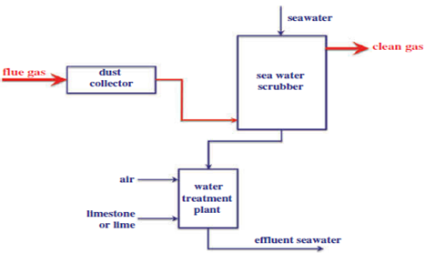
FGD systems are growing in demand and popularity as they are able to control SO2 emissions in coal fired power plants. For power plants located at coastal areas, utilization of seawater from the cooling system of the plant to scrub SO2 is an attractive alternative to using other alkaline chemicals such as limestone and magnesium hydroxide which would incur a continuous procurement cost which is undesirable. The basics of FGD operation are described as follows: SO2 is absorbed by a counter-flowing seawater stream, after which it is oxidized to sulphate by blowing air (oxygen) into the stream. Before discharging, the neutralization process was take place when the acidified from seawater effluent is used in mix up with the present seawater of bicarbonates. The chemical process was undergoing accordingly.
Comparing with the existing FGD system which use the wet limestone system, the seawater FGD system compromise with several advantages including the process, efficiency and economically saving in operation and maintenance. Sea water scrubbing is the most economical FGD process for removing SO2 from flue gases for the cases of power stations which located close to the sea. In this process, seawater is used to absorb SO2 due to the two key properties of sea water. The process begins with the existing bicarbonates which is already alkaline in the seawater. The reaction of alkaline bicarbonate and response to the addition acid. The process continuously reacts to absorbed SO2 with transformed into natural chemical of seawater, sulphate ions. Figure
The two important stage of sulphur dioxide was present in the water and perform as sulphite. Acidic condition is performing where the sulphate and hydrogen is containing in chemical composition. Thus, the seawater as natural alkaline agents are used in the process by mixing before discharging to the open sea ( Ryan & Ledda, 1997). The chemical reaction process is stated below:
SO2 + H2O SO24 + H2 (1)
SO2 + O2 SO24 (2)
As mentioned, the FGD system installed in power plant to control SO2 emission within acceptance limit. Due to that, the study intent to investigate the relationship of coal sulphur content in the sub-bituminous coal to the SO2 come out at the stuck in the flue gas as combustion product.
Research Methods
For the purpose of this research, the study was carried out in coal fired thermal power plant located in Malaysia. The plant, which was connected to the national grid since 2003, features a sub-critical boiler with reheat at a nominal rated power output of 700MW. Table
As stated in the Table
Sub-bituminous coal
There are six types of sub bituminous coal is used for this study. The coal analysis involves with ultimate analysis and approximately analysis was carried at the coal supplier laboratory before depart to the thermal plant coal yard. As mentioned before, the coal quality measurement was carries out thru proximate analysis and ultimate analysis according to the international standard such as IEA coal sampling and analysis standard and ASTM Coal Sampling Standards. The coal quality parameters and coal characteristic was presented in the coal certification analysis, then. For the purpose, the certificate of analysis (CoA) contains relevant information about the coal composition for a particular batch of coal types. Table
Measure sulphur contents
The origin of Sulphur contents with sea water, mineral from the fresh water, vegetation with additional of superfluous material. After transforming from syngeneic process to epigenetic process through the ground water, the second phase of coal sulphur was present. During the process, the organics sulphur and inorganic sulphur is performing when the originate sea water in the coal decrease. The chemical reaction take place and separately firm as organic and inorganic sulphur. According to Ryan and Ledda ( 1997), maceral structure of coal consists with organic sulphur which is between 0.1 to 0.5 percent from the total weight.
For this study, ASTM D4239-14 method was applied in measuring the sulphur content in coal. The tube furnace with high-temperature used to determine the sulphur content from coal sampling. Pulverized coal sampling, size 250-μm was used for both methods which is at different temperature.
Combustion Method A (1350 °C): Pulverized coal sampling was tested with minimum operation temperature at 1350°C in the tube furnace. Sulphur dioxide was presented after decomposed and oxidized during combustion process in the tube furnace. Thus, Infrared (IR) absorption detector is used to measure the Sulphur dioxide as the element of combustion product. In addition, the calibrated sulphur analyzer was used in comparing the results; BBOT (2,5-di 5-tertbutylbenzoxazol- 2-yl) thiophene, C26H26N2O2S). The sulphur analyzer with pure substance about 7.47 percentage of sulphur was used for calibration purposes.
Combustion Method B (1150 °C): Pulverized coal sampling was tested with minimum operation temperature at 1150°C in the tube furnace. The tube furnace with stream of oxygen burned in a quartz combustion temperature with excess the tungsten trioxide (WO3). During the combustion process in the furnace, the sulphur was present after oxidizing process at the WO3 temperature. The result of sulphur contents in sub-bituminous coal is comparing by using the sulphur analyzer.
FGD process
In order to monitor and control the effectiveness of the FGD system, parameters for FGD system was measure during the experiment, such as firing time of the coal, FGD operational status as well as the amount of SO2 released to the atmosphere. As mentioned before, the FGD plant is installed to the thermal coal plant in order to minimize the SO2 production in the flue gas outlet. The amount of SO2 production in the flue gas outlet is subject to the amount of sulphur content in the coal. The FGD system could be put in service and take off which is relatively refer to sulphur content in the flue gas. Economically, the FGD system can be taking off without affecting the power plant generation process if the sulphur contents produce within the acceptance limits. The FGD plant consists of one gas handling system and an associated seawater treatment system. For this thermal plant, the FGD is designed only to treat 65 percent of the total flue gas flow.
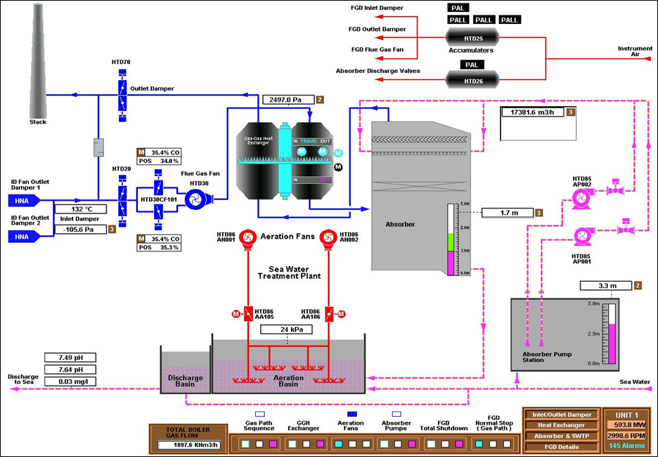
The flue gas duct from the outlet of each ID fan is merged into one duct, hereafter named the main duct. From here, up to 65 percent of the flue gas may be routed through the FGD inlet damper by the action of the FGD Flue Gas Fan. The FGD Flue Gas Fan boosts the pressure in the flue gas sufficiently to overcome the pressure drop through the FGD system. Guide vane control is used to adjust for the correct flue gas flow through the FGD Flue Gas fan. Downstream the fan, the gas enters the gas-gas heat exchanger (GGH). The untreated flue gas enters the GGH at the top, and flows downward through the GGH to the absorber inlet ( TNBJ Operation & Maintenance Manual, 2003).
The flue gas enters the absorber in the bottom section. The absorber is designed as a packed tower. Seawater is introduced above the packing in the absorber top section. Subsequent to passing through a mist eliminator, the treated gas leaves the absorber through the top, and enters the lower section of the GGH. In the GGH heat from the untreated hot gas is transferred to the cold treated gas coming from the absorber. The reheated gas passes the FGD outlet damper before it is mixed with the remainder of the hot, untreated bypass gas in the main duct. The temperature thus increases further to reach the design value. The flue gas is subsequently conducted to the stack. In cases of emergency situations that require shutdown, the FGD plant may be 100% bypassed. The main duct will, in such a situation, transport all the flue gas directly to the stack. This situation will imply trip of the FGD flue gas fan/closing of the guide vane dampers, succeeded by closing of the FGD inlet- and outlet dampers ( Oikawa, Yongsiri, Takeda, & Harimoto, 2004). Figure
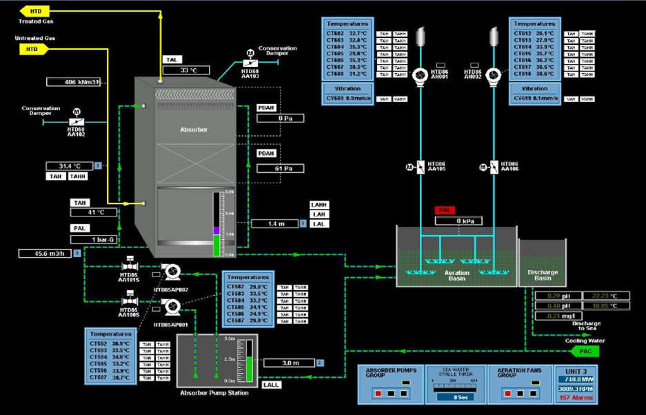
SO2 is removed from the flue gas by virtue of bringing into contact seawater and flue gas through the counter current flow within the absorber packing ( Oikawa et al., 2004). As a result, SO2 is trapped and transferred to the seawater. The seawater treatment plant which is aeration basis - oxidases the seawater rich with SO2 to harmless sulphate prior to discharge back into the sea by blowing into the seawater. At the same time, the pH of the seawater discharge back to the sea is also raised.
Findings
Six types of sub bituminous coal were used for firing in the furnace and continuously generating 700 megawatts. For each types of coal, the units were continuously generating 700 megawatts, without no load reduction, no load deration within 5 days. Boiler parameters performance was measured during the experiment period; average load generation, temperature for superheated steam, temperature for reheat steam, temperature for metal superheater tube, temperature for metal reheater tube, economizer outlet temperature, flue gas outlet temperature, superheater spray water, and reheater spray water. The boiler parameters performance is closely monitored during the experiment because its indicates the boiler efficiency and abnormalities. Table
From the boiler performance parameters presented in the table, shows normal value throughout firing all the six various of sub-bituminous coal within 5 days. Boiler was good performing in producing maximum loading about 700MWn. Superheater spray water and reheater spray water operation in minimal opening which is less than 85 tonnes per hours for six selected types of sub-bituminous coal. Directly, the spray water indicates the heat transfer was sufficiency performing in the furnace. Besides, the critical parameters such as temperature at superheater steam, temperature at reheat steam, metal temperature at superheater and metal temperature at reheater values behaviours within the acceptance operation limit, which is 540°C. Meanwhile, the flue gas outlet temperature come out from the furnace for each types of sub-bituminous coal recorded different temperature reading which is between 171 to 182°C. In average, the plant efficiency is about 35 percent during presenting this study.
In general, the flue gas outlet temperature is affected by coal properties, slagging and fouling index, based acid ratio, ash contents and fuel air ratio. As mentioned before, the plant efficiency during the experiment is about 35 percent in average which describes the percentage of the total energy used in fuel for the power plant to produce the electricity to the national grid. This is normal values for plant efficiency which are applied around the world ( Nuraini et al., 2018). The balance of generated energy lost to the environment as unused heat or perform as district heating in surrounding.
Table
FGD data captured represent the FGD performance and efficiency in operating the SO2 process. As mentioned before, SO2 is removed from the flue gas by virtue of bringing into contact seawater and flue gas through the counter current flow within the absorber packing. The mist eliminator plays the important roles to the environment. The gas-gas heat exchanger (GGH) operating to cool the untreated flue gas from the FGD before it enters the absorber and increase and increase the temperature of the treated gas before it is discharge to the stack. The untreated flue gas in the absorber will go throughout mist eliminator. The mist eliminator functions to trap the droplets from discharging to the environment. The more efficient the mist elimination, the less risk there is of wasting energy through clogged heat transfer surfaces. By looking at the table above, absorber mist different pressure recorded normal reading which are in range. The absorber outlet temperature is measured purposely to meet the requirement before discharge to the open sea. Therefore, the effectiveness of overall process is determining by the mist eliminator. Efficient of mist eliminator increase the effectiveness of FGD system operation, fully function. Besides, the mist eliminator protects and prevent the equipment and infrastructure of the FGD system from corrosion. Economically, its extending the life cycle of the plant to be in service.
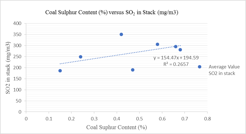
From the study, the SO2 distribution in flue gas outlet is increase with the SO2 production in stack. Figure
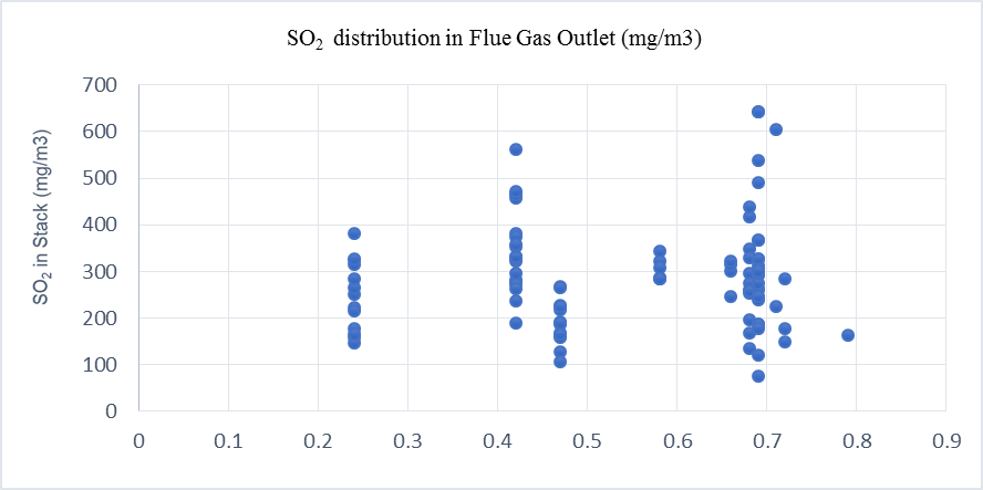
The relationship between coal sulphur content to the SO2 production in stack represented in Figure
Conclusion
The FGD system process about 50-70 percent of total flue gas outlet from the combustion in furnace. FGD system successfully reduce the SO2 emission and comply with the CAR 2014, Malaysian act. The study was found the linear correlation on the sulphur content in coal to SO2 production at stack. The higher sulphur content in sub bituminous coal, the higher sulphur production during combustion in furnace and result the high SO2 at stack. However, the high efficiency FGD process SO2 production at stack will reduce accordingly. Eventually, the industry can predict SO2 in advance. Besides that, the FGD system utilization can be sufficient to improve the SO2 emission. Figure
As mentioned by Srivastava and Jozewicz ( 2001), SO2 emissions are known to have detrimental impacts on the human health and the environment. Many flue gas desulphurization (FGD) methods, such as wet limestone FGD process, have been developed and put into use in the coal-fired power plant. However, there is very few methods that could achieve desulphurization and decarburization simultaneously from the coal-fired flue gas. In removing SO2 from exhaust flue gases through flue gas desulphurization (FGD) it can be too easy to miss a golden opportunity to enhance profitability.
References
- Mustafa, M. (2012). The Environmental Quality Act 1974: A Significant Legal Instrument for Implementing Environmental Policy Directives of Malaysia. IIUM Law Journal, 19(1).
- Nuraini, A. A., Salmi, S., & Aziz, H. A. (2018). Efficiency and Boiler Parameters Effects in Sub-Critical Boiler with Different Types of Sub-Bituminous Coal. Iranian Journal of Science and Technology, Transactions of Mechanical Engineering, 1-10.
- Oikawa, K., Yongsiri, C., Takeda, K., Harimoto, T. (2004). Seawater flue gas desulfurization: Its technical implications and performance results. Environmental progress & sustainable energy, 22(1), 67-73.
- Poullikkas, A. (2015). Review of Design, Operating, and Financial Considerations in Flue Gas Desulfurization Systems. Energy Technology & Policy, 2(1), 92-103.
- Ryan, B. C., & Ledda, A. (1997). A Review of Sulphur in Coal: With Specific Reference to the Telkwa Deposit, North- Western British Columbia. Geological Fieldwork, Paper 1998-l.
- Spitz, N., Saveliev, R., Perelman, M., Korytni, E., Chudnovsky, B., Talanker, A., & Bar-Ziv, E. (2008). Firing a sub-bituminous coal in pulverized coal boilers configured for bituminous coals. Fuel, 87(8-9), 1534-1542.
- Srivastava, R. K, & Jozewicz, W. (2001). Flue gas desulfurization: The state of the art. J. Air & Waste Manage. Assoc., 51, 1676-1688.
- TNBJ Operation & Maintenance Manual (2003). Thermal Coal Plant, Tenaga Nasional Berhad. TNB Janamanjung Sdn Bhd (TNBJ)/ Manjung.
Copyright information

This work is licensed under a Creative Commons Attribution-NonCommercial-NoDerivatives 4.0 International License.
About this article
Publication Date
30 March 2020
Article Doi
eBook ISBN
978-1-80296-080-8
Publisher
European Publisher
Volume
81
Print ISBN (optional)
-
Edition Number
1st Edition
Pages
1-839
Subjects
Business, innovation, sustainability, development studies
Cite this article as:
Salmi, S., Nazrin, Z., & Nuraini, A. A. (2020). SO2 In Flue Gas Desulphurization For Different Types Of Sub-Bituminous Coal. In N. Baba Rahim (Ed.), Multidisciplinary Research as Agent of Change for Industrial Revolution 4.0, vol 81. European Proceedings of Social and Behavioural Sciences (pp. 711-722). European Publisher. https://doi.org/10.15405/epsbs.2020.03.03.83