
Intelligent Self-Defence Device (Insed)

Abstract
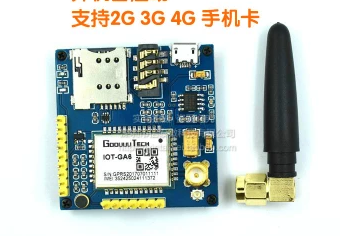
Number has reported Malaysia is ranked at a jaw-dropping top 15th in World.. That was in 2016. Peoples are feeling unsafe due to increasing crimes. Intelligent self-defence device or InSeD upholds the principle of improving and solving the problem related to self-defence device among peoples in Malaysia. We propose a quick responding mechanism that helps woman during trouble. The system was presented in prototype size for illustration. The device was designed with emergency buttons where user can press when she/he feels, threatens and sends the location information as a Short Message Service(SMS) alert to emergency. In our project SMS is sending by using normal Nano Sim card with a Global System for Mobile (GSM) SIM900A module. This GSM module enables the user to send message, receive message, make call and hang up call. To provide user Global Positioning System (GPS) location to user’s emergency contact number a GPS Neo6M2 module is installed inside our product. The GPS size is small and user friendly so it won’t take space in product’s prototype. There is a simple keypad on the product to enable user key in pin number to stop the alarm, this is the only way to stop the alarm. An Arduino Uno is used as a microcontroller. C++ code is used to set the emergency contact number and the pin number for the user.
Keywords: Intelligence deviceprototypeself-defenceArduino Uno
Introduction
One of the biggest challenges facing the Government at this moment is security. Now, the level of security for the country is at a low level because the low efficiency of police and poor security system in public area. In Malaysia, self-defence device that can harm others is illegal according to Section
Thus, from the above list shows that even electroshock weapon or stun guns are illegal to be used by public without any license under the Arms Act 1960 ( Worley & Worley, 2017). So, self-defence device like InSeD is needed by everyone. Public area is hundred times dangerous compare to public place that’s why a self-defence device is needed by anyone. A good functional of a personal alarm is by activating it, and then drop it on the floor near the assailant before run away. Maybe this is a good alarm but still has several parts, can be improves. GPS module is built in inside the device this function enable the user get help from others by sending out the user’s GPS location. This function is enabling police come to help the user by tracking the GPS location from the GPS module. GPS module also enables product user to send his/her GPS location anytime anywhere.
For sending message purposes, we used GSM module to send the signal out instead of Wifi (Wireless Fidelity) Module or Bluetooth module, because those two modules only can work in specific situation. Wifi Module only can work in Wifi coverage area and Bluetooth module will only work in a very short distance. ( Yılmaz & Özyer, 2019). The reason why we choose GSM module is because GSM module enables to send message in any situation as long as the Subscriber Identification Module (SIM) card located inside the GSM module still has enough credit. Besides, GSM module enables to send SMS to other device by ignoring the distance between.
Safety and security among teenagers and young adults are a major issue related to crimes and harassment ( Coe & Rönnblom, 2019). In this project, the user can directly send their location to parents or police and activate the alarm once they felt threaten to capture the attention of the people nearby for help. This can be done with interface between the keypad, GPS and GSM module. GPS module will give the current location to particular registered number while GSM module sends the message to the pre-defined numbers.
Problem Statement
A large size of device will cause difficulty to the user. It will increase the weight of item. The user may prefer not to bring it along. This will resist the user to attain help during emergency. Another issue was normal self-defence alarm. There is no signal send out when output of the triggered self-defence device is just 120 db of sound. Villain is able to throw away the device or force shut down the device. Thus, no GPS or any message is able to send out from the device. No one will know the user is in danger.
Research Questions
-
How to reduce the criminal risk in the society
-
What is the advance technology able to be implemented?
-
How does the project give the impact to the potential market?
Purpose of the Study
-
To create a portable intelligent device that can carry by any age with considerate price.
-
To develop an intelligent device that able to send current GPS location to emergency contact number.
Research Methods
An online survey was conducted as a medium of data collection tool to gather information about potential self-defence device user individuals regarding their views and opinions on the product functions and performance. This approach was to provide specific insights on designing an intelligent self-defence device specification that would be practically realizable in Penang or maybe whole Malaysia. We aimed to find out the requirements of self-defence device among young people. The participant’s ages were between 13 to 23 years old. Among them 22 were males and 18 were females.
The survey shows that 82.5% of them have used self-defence device before. Only 17.5% never used the device. From the pie chart, it is clear that the majority of them about 87.5% prefer to utilize the self-defence device. Based on the review about 90% of the participants were attracted in buying the self-defence device. Only a small minority preferred not to utilize the device. We can say that, the self-defence device is certainly accepted among the participants. We can almost certainly predictable to see more people attracted in buying self-defence device when they are put up for sale.
Findings
Fabrication of Mechanical Components
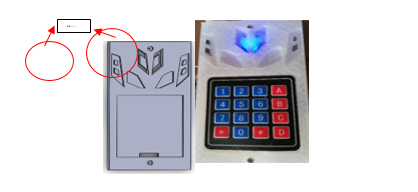
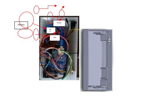
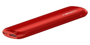
The device’s design is based on the requirement of the end-user where it first needs to be smaller for easier to carry along with the user and lighter for easier to store with the user. The first design is a bit bulky in size because of still under development without any dimension from all components. It also used ultrasonic sensor to detect the incoming criminals who approached from behind. Unfortunately, the ultrasonic sensor is not practical for this usage as it will detect anything that come close to the device. In future development, with the help of Artificial Intelligence (AI), this device can detect the movement of criminals who approaching the user by learning the pattern of movement of a criminal. Next, the latest and final design of the device has removed the ultrasonic sensor, much smaller in size and more attractive in design which also from the requirement of end-user. It used the smaller power bank as its power supply because it is much easier to recharge and has the power indicator which will tell the user its power left. Figure
As shown in Figure
As shown in Figure
Hardware Control Units and Required Modules
A. Control Unit
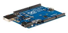
The Arduino Uno is a microcontroller board which operated according to the ATmega328. These are the features of Arduino Uno:
The operating voltage needed is 5V. Input Voltage (recommended) 7-12V and Input Voltage (limits) 6-20V.
There are 14 Digital I/O Pins (of which 6 provide Pulse Width Modulation (PWM) output), 6 Analog Input Pins and the DC Current per I/O Pin is 40 Ma. 0.5 KB used by boot loader SRAM 2 KB (Atmega328) and EEPROM 1 KB (Atmega328).
The clock Speed is 16 MHz.
The Arduino software includes a serial monitor which allows simple textual data to be sent to and from the Arduino board. It is chosen due to its low cost, simple and clear programming environment and easy to use. Figure
SIM900A Modem is built with Dual Band GSM/General Packet Radio Service (GPRS) based SIM900A modem from SIMCOM company as shown in Figure
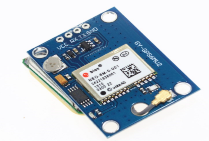
The NEO-6 module series is a family of stand-alone GPS receivers featuring the high performance u-blox6 positioning engine. The picture of the GPS module is shown in Figure
B. User interface and display unit
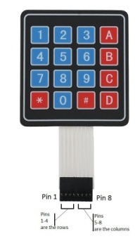
Figure
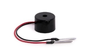
Buzzer is a component used to produce sound. In our project we will use a buzzer which smaller size which is able to produce high volume of sound. When button “A” is pressed it will trigger buzzer, buzzer will start to release high volume of sound until correct pin number is entered. Figure
C. POWER SOURCE
Figure
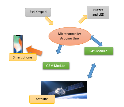
Block Diagram
Figure
Discussion
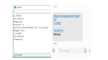
Mode A:
Button ‘A’ will miss called the emergency contact for 10 seconds to alert the contact and will hang up then will send the location of the device through normal message. The 10 second miss call is to ensure the emergency message can be seen. Message sent out is not immediate it will take around 10 second for the phone to receive the message. It also will turn ‘ON’ the alarm to alert the surrounding of the user in emergency cases with an indication of ‘Dangerous’ which means the user in danger. When the emergency mode is on, the buzzer will start ringing until correct pin number is entering through the keypad. The result of Mode A is shown as Figure
Mode B:
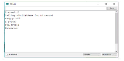
Button ‘B’ will also call the contact for 10 seconds and hang up then it will send location message to the contact, the message receive by emergency contact is the same but the only different to mode “A” is it does not turn ‘ON’ the alarm. This is crucial for situations where the user could not make any noise or does not want to alert the criminal with an indication of ‘Dangerous’ which means the user in danger. At the same time Led on InSeD will off for 2 seconds to inform the user the mode “B” is on. The result of Mode B is shown as Figure
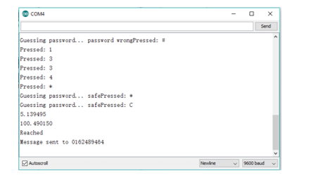
Mode C:
Button ‘C’ function to tell the contact the user has reach specific location through the message with an indication of ‘Reached’. When button C is pressed Arduino will start getting the GPS location from GPS module in chat form and GSM module is ready to function. After get the GPS location, the GSM module will send a message tell to inform the user are reached destination safely. The result of Mode C is shown as Figure
Mode D:
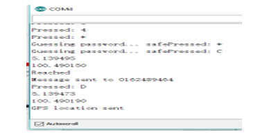
Lastly, button ‘D’ only send location to the contact without any indication the user in any dangerous situation. The result of Mode A is shown as Figure
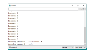
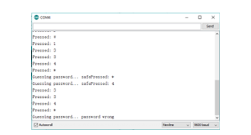
This device also implements the keypad for the safety of the user to turn ‘OFF’ the alarm by inserting the password set into this device which only the user knows. In this code, it is set the ‘#’ acts as reset passwords, ‘*’ acts as enter, and the passwords are ‘1, 3, 3 and 4’ as shown in Figure
Conclusion
Being safe and secure is the demand of the day. This design will help users to be secure. The proposed mechanism provides viewing the location of the victim which can further be tracked using Google maps with emergency buttons with the different mode where they can press when they feel insecure. So, user’s contact person can call to the user to confirm the safety of users. If something wrong happens, they make a report to police with user’s GPS location, so police can more efficiently help us. This system is one of the steps or solutions for self-defence and helps to decrease the crime rate against.
Acknowledgments
We would like to express our greatest appreciation the principal investigator for USM Short Term Grant 304/PELECT/60313049 to support the project in publishing the manuscript.
References
- Coe, A. B., & Rönnblom, M. (2019). Collective caring: creating safety through interactions between young activist groups and young adults in Sweden. Journal of Youth Studies, 22(6), 839-855.
- Duwe, G. (2018). Can circles of support and accountability (CoSA) significantly reduce sexual recidivism? Results from a randomized controlled trial in Minnesota. Journal of experimental criminology, 14(4), 463-484.
- Murray, K. (2018). The modern making of stop and search: The rise of preventative sensibilities in post-war Britain. The British Journal of Criminology, 58(3), 588-605.
- Worley, V. B., & Worley, R. M. (2017). Smart weapons need smart policies: Municipal liability for inappropriate use of tasers and stun guns by police officers. Criminal Law Bulletin, 53(1), 34-60.
- Yılmaz, E., & Özyer, S. T. (2019). Remote and Autonomous Controlled Robotic Car based on Arduino with Real Time Obstacle Detection and Avoidance. Universal Journal of Engineering Science, 7(1), 1-7.
Copyright information

This work is licensed under a Creative Commons Attribution-NonCommercial-NoDerivatives 4.0 International License.
About this article
Publication Date
30 March 2020
Article Doi
eBook ISBN
978-1-80296-080-8
Publisher
European Publisher
Volume
81
Print ISBN (optional)
-
Edition Number
1st Edition
Pages
1-839
Subjects
Business, innovation, sustainability, development studies
Cite this article as:
Abdullah, N., Yusuff, H., Leong, L. K., Fahimi, M., Aisha, S., & Aidil, E. (2020). Intelligent Self-Defence Device (Insed). In N. Baba Rahim (Ed.), Multidisciplinary Research as Agent of Change for Industrial Revolution 4.0, vol 81. European Proceedings of Social and Behavioural Sciences (pp. 683-693). European Publisher. https://doi.org/10.15405/epsbs.2020.03.03.80