
Cast Iron Green Machining

Abstract
The main activity of the metal cutting industry is machining various kinds of metal materials to make various products such as bolts, couplings, gears, shafts, bearings, turning metal casting objects and other engine components for sale in the local market as well as for export needs. Cutting fluid (coolant) is often used for metal machining to obtain a long tool life and low machined surface roughness, but the use of such coolant has a negative impact on machine operators and environment. The negative impact on operators is cause lung disease and temporary skin disease while for the environment, it will cause environmental pollution because coolant from synthetic materials cannot be decomposed in nature. Due to this reason, scientists are trying to eliminate the use of coolant on metal machining. In this study, a dry machining test is performed on cast iron with 8 (eight) varying cutting conditions (2 3factorialmethod), as follows V 1, V 2, f 1, f 2, a 1, a 2. In this test, some information can be collected such as toolwear (VB), machining time (t), surface roughness (Ra), machining length (L), machining volume (Q) and material removal rate (MRR). The test data are then analyzed to obtain optimum cutting conditions for the 8 (eight) cutting conditions to be applied to environmental friendly machining (green machining).
Keywords: Coolantcast irongreen machining
Introduction
Machining process or metal cutting process is the main activity carried out by small and medium metal industry by using conventional machine tools ( Nasution, Ginting, Hamsi, & Harahap, 2005). This machining process is intended for manufacturing engine components or other equipment ( Cerce & Pusavec, 2016; Nugroho & Senoaji, 2010)
Green machining is desirable for environment and it will be considered as a need in the upcoming future for manufacturing companies. For the protection of environmental laws and health regulations industries will be forced to consider dry machining. The benefits of dry machining includes: non-pollution of the atmosphere (or water); no left over on the swarf which will be displayed in reduced disposal and cleaning costs; no threat to health; and it is non-injurious to skin and is allergy free. And it also offers cost reduction in machining ( Jain & Kansal, 2017; Nasution et al., 2005).
In high speed machining the coolant cannot reach the tool-chip interface, so it has no effect on the heat that occurs, in addition, the cooling liquid is not environmentally friendly, so it is necessary to make a law on machining that directs the metal cutting industry players to cut dry or green machining ( Amini, Khakbaz, & Barani, 2015; Gaafer, Ghaith, Khalil, & Mostafa, 2015).
When cutting metal, coolant has an important function to remove chips on the workpiece. Thus, the use of coolant is very possible in high performance operations, while the function of coolant is not available in dry cutting, this means that there will be more friction and adhesion between the cutting tool and the workpiece. Cutting tool and Specimens will experience a higher thermal load. This can result in a high level of tool wear, for example the process of forming a crater wear on cutting cast iron using an uncoated carbide tool ( Galanis, Manolakos, & Vaxevanidis, 2008; Nayyar, Kaminski, Kinnander, & Nyborg, 2012).
Basically, in a normal machining process, the process of dumping waste into the environment in a solid, liquid or gas condition, as a result of processes involving chisels, workpieces and coolasnt, While machining systems using cutting tools require a certain amount of power associated with machining activities as well as non-machining, usually, research studies are directed at cutting energy in the machining system, where a certain amount of energy is needed to remove a certain amount of material. However, from the point of view of green machining, the energy consumption used must be considered as a whole not limited to only cutting energy ( Lee, Tarng, & Li, 2000; Nugroho & Senoaji, 2010).
Problem Statement
Generally, small-medium metal industry still uses coolant which has negative impact on lathe operators such as cause skin and lung diseases, as well as negative impacts on the environment because coolants are made from synthetic materials which are very difficult to be decomposit ( Jain & Kansal, 2017). No use of coolant will reduce production costs ( Amini et al., 2015).
However, dry cutting may also show positive effects such as thermal shock reduction and thus in the formation of comb-cracks. Higher machining temperatures influence also chip formation. This may results in both ribbon chips and snarl chips. When reliable control over chip formation is required, it may be necessary to use cutting inserts with especially adapted chip shaping grooves towards dry cutting (GLANIS).
Research Questions
In this study, coolant was not used, the research question ( Galanis et al., 2008) are:
Will the tool wear according to standard be obtained?
Will surface roughness according to standard
Will good productivity be obtained?
Purpose of the Study
To obtain a cutting condition without coolant which has tool wear and roughness according to good standards and productivity.
Research Methods
Material
The material to be used in this study is the type of cast iron material with the mechanical properties of the following test results: 229 HB hardness, 396 mPa tensile strength and chemical composition as follows: Cr = (0.05 - 0.45)%; Cu = (0.15– 0.4)%; Mn = (0.5–0.9)%; Mo = (0.05-0.1)%; Ni = (0.05 - 0.2)%; P = Max 0.12%; C = (3.25-3.5)%; S = Max 0.15%; Si = (1.8-2.3)%.
The material used in this study is the type of Cast Iron material with a diameter of 75 mm and a length of 300 mm (see Figure

The lathe equipment used in the small and medium metal industry where the research was conducted was a CNC EmcoTurn-242 lathe.
CNC Lathe
The lathe equipment used in the small and medium metal industry where the research was conducted was a CNC EmcoTurn-242 lathe (see Figure
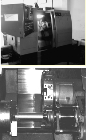
Caption :
Workpiece Clamp
Tool
Tool Holder
Tool Post
Center
Workpiece
This CNC machine is used for cutting workpieces with cutting condition variations as in table
In Table
Data Collection Method
The data was collected on workpiece cutting using 2 3 factorial method. According to provisions of ISO 36854, all cuts stop at the time of tool wear (flank wear) have reached 0.3 mm. The cutting data is plotted graphically which will show the effect of cutting parameters combination ( Cerce & Pusavec, 2016).
Findings
Cutting conditions without coolant carried out to obtain tool performance and machining productivity with 2 3 Factorial method. The cutting conditions were by varying cutting conditions with the lower limit (CC1) and upper limit (CC8), as shown in table
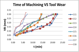
Time Machining and Tool Wear
Based on tool wear and tool life, Figure
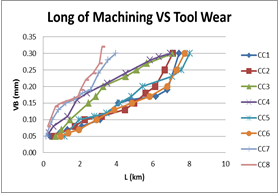
Based on the relationship between cutting length and tool wear as shown in Figure
Time Machining and Tool Wear
Figure
Cutting Volume (Q)
Figure
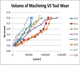
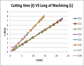
Based on the relationship between cutting length with cutting time (see Figure
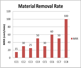
Material Removal Rate
From Figure
Conclusion
After analyzing all graphs generated from the experiment, the optimal cutting conditions to beapplied at green machining (without coolant) is cutting condition -2 (CC2) with v = 200 m/minute, f = 0.15 mm/rotation and a = 1 mm. Material Removal Rate is 30 cm 3/minute. This is caused by:
The tool life generated is included in the standard criteria.
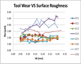
Surface roughness produced according to standards.
Superior from side Machining length and machining volume
The resulting MRR falls into the middle criteria.
Acknowledgments
The authors wish to acknowledge the Directorate of Research and Community Service, Directorate General of Strengthening Research and Development at the Ministry of Research, Technology and Higher Education, Republic of Indonesia.
References
- Amini, S., Khakbaz, H., & Barani, A. (2015). Improvement of near-dry machining and its effect on tool wear in turning of AISI 4142. Materials and Manufacturing Processes, 30(2), 241–247. https://doi.org/10.1080/10426914.2014.952029
- Cerce, L., & Pusavec, F. (2016). Increasing machinability of grey cast iron using cubic boron nitride tools: Evaluation of wear mechanisms. Indian Journal of Engineering and Materials Sciences, 23(1), 65–78.
- Gaafer, A. M., Ghaith, M. H. G., Khalil, T., & Mostafa, A. A. (2015). The Effect of Machining Parameters on the Cutting Forces , Tool Wear , and Machined Surface Roughness of Metal Matrix Nano Composite Material, 4(3), 43–50. https://doi.org/10.11648/j.am.20150403.11
- Galanis, N., Manolakos, D., & Vaxevanidis, N. M. (2008). Comparison between dry and wet machining of stainless steel. Retrieved from https://www.researchgate.net/profile/Nikolaos_Vaxevanidis/publication/251870152_COMPARISON_BETWEEN_DRY_AND_WET_MACHINING_OF_STAINLESS_STEEL/links/0deec522125e7e6280000000.pdf
- Jain, A., & Kansal, H. (2017). Green Machining – Machining Of The Future. In 4th National Conference on Advancements in Simulation & Experimental Techniques in Mechanical Engineering (NCASEme-2017). Retrieved from https://www.researchgate.net/profile/Harsh_Kansal/publication/314238257_Green_Machining_-_Machining_Of_The_Future/links/58bd0618a6fdcc2d14e59735/Green-Machining-Machining-Of-The-Future.pdf
- Lee, B. Y., Tarng, Y. S., & Lii, H. R. (2000). An investigation of modeling of the machining database in turning operations. Journal of Materials Processing Technology, 105(1–2), 1–6. https://doi.org/10.1016/S0924-0136(00)00535-5
- Nasution, A. H., Ginting, A., Hamsi, A., & Harahap, B. (2005). Analisa parameter pemotongan terhadap peningkatan produktivitas industri logam kecil menengah. Retrieved from http://repository.usu.ac.id/bitstream/handle/123456789/15838/sim-apr2005-%20%282%29.pdf?sequence=1&isAllowed=y
- Nayyar, V., Kaminski, J., Kinnander, A., & Nyborg, L. (2012). An experimental investigation of machinability of graphitic cast iron grades; Flake, compacted and spheroidal graphite iron in continuous machining operations. Procedia CIRP, 1(1), 488–493. https://doi.org/10.1016/j.procir.2012.04.087
- Nugroho, S., & Senoaji, K. (2010). Karakterisasi Pahat Bubut High Speed Steel (Hss) Boehler Tipe Molibdenum (M2) Dan Tipe Cold Work Tool Steel (a8). Rotasi (Semarang), 12(3), 19–26. https://doi.org/10.14710/rotasi.12.3.19-26
Copyright information

This work is licensed under a Creative Commons Attribution-NonCommercial-NoDerivatives 4.0 International License.
About this article
Publication Date
30 March 2020
Article Doi
eBook ISBN
978-1-80296-080-8
Publisher
European Publisher
Volume
81
Print ISBN (optional)
-
Edition Number
1st Edition
Pages
1-839
Subjects
Business, innovation, sustainability, development studies
Cite this article as:
Nasution, A. H., Harahap, M. R., & Napid, S. (2020). Cast Iron Green Machining. In N. Baba Rahim (Ed.), Multidisciplinary Research as Agent of Change for Industrial Revolution 4.0, vol 81. European Proceedings of Social and Behavioural Sciences (pp. 639-647). European Publisher. https://doi.org/10.15405/epsbs.2020.03.03.74