
Design Of Experiment Approach On Vibration Characteristics In Automobile Crankshaft

Abstract
This research presents a method to optimize crankshaft structure under frequency domain. The crankshaft for passenger car for four–cylinder internal combustion engine is used in the analysis. The purpose of the analysis was to obtain the optimum crankshaft which improves vibration response. This study is important to obtain a low crankshaft vibration and at once give comfortable to the passenger. Optimization phase was initiated at bearing boundary condition by using a design of experiment. Design of experiment (DOE) was utilized to determine the parameters that affect the level of vibration. Results achieved from the experimental design then are used for the optimizing of crankshaft vibration level reduction. Crankshaft geometrical parameters were modified while Young’s modulus and the main journal diameter were maintained as original values. Structural modification was performed to be compatible with the engine assembly equipment. After the modification it found, the vibration response level of crankshaft structural was reduced to 38% in the range of frequency 0 to 1600 Hz. The levels for vibration responses were successfully reduced and the natural frequencies were also had shifted towards a higher frequency domain. The research outcomes showed the improvement of the crankshaft vibration response level with the optimized crankshaft would provide a feasible approach for robust design for the automobile crankshaft.
Keywords: Model AnalysisStructural ModificationDesign of ExperimentCrankshaft
Introduction
Automobiles become one of the daily essentials in worldwide applications as demands on fast, convenient and adequate transportation are increasing. Ever since automotive vehicles were produced: designers, scientists and engineers are always attempting to improve vehicle manufacturing with advanced technology and materials. Nowadays, innovative design developments on vehicle manufacturing are growing rapidly to increase lifetime of an engine and better passenger comfort. The performance of engines and transmissions also increased since advanced automations and machinery are applied in industry as well as considerations of environmental impacts are taken in effect. (Mahendrakar & Kulkarni, 2016, Rebbert, Cevik, & Maassen, 2010).
Besides that, obtaining a good performance of crankshaft with low vibration through an accurate process and precise inspection for high reliability satisfaction is not an easy. The process will take non-limit period of time especially when the analysis is conducted in time domain. Therefore, it is obviously important to conduct the analysis in frequency domain. Modification can most easily be made in the design stage in an effort to eliminate vibration, when necessary or to reduce it as much as possible. They struggle to make a competitive design, safely and economically. In this situation, researches and engineers often rely on trial and error process. The industry recognizes that, the only way to overcome these kinds of challenges is to acquire a fundamental understanding of the independency all elements of the system. This means the phenomena of vibration occurs even though the automobile engine has different shapes of crankshaft.
For a specific vehicle engine, the customized crankshaft is designed for each product. When designing a crankshaft for a four-stroke engine, the system includes four crank throws attached with the four pistons which is generally linked to the flywheel. Thus, these crank throws operate as a lever arm for the piston to reciprocate and thereby generating rotational motion during the engine combustion cycle. The purpose of crankshaft is to transmit heavy loads of the flywheels and internal gaseous pressure of the engines at a very high rate. So, if any fault arises in the crankshaft, it must be alarmed & noticed by the operator or driver timely, to avoid the mass damage or catastrophe (Mahendrakar & Kulkarni, 2016). Internal combustion engine is the concentrated mass in whole vehicle as well as crankshaft is key component of an engine so that it will generate vibration and transfer to the attached vehicle body structures. Passenger comfort, driving stability and NVH are main factors for performance of automobile which are affected from engine vibration. Engine vibration nature depends on gas pressure in misfire condition, unbalanced masses and structure resonance characteristics from reciprocating and rotating engine components. Severe vibration can create unstable conditions regarding on speed, fuel consumption and service life of an engine. Every part of an engine is crucial for ideal system of combustion process. For safety and passenger comfort, it is critical how much values and what kind of vibration delivers from road to car body (Burdzik & Dolecek, 2012). To stabilize the vehicle or machine, the engine must stabilize first. Among various engine parts, crankshaft is a critical component in power loom system if it undergoes breakage the entire system will stop, therefore it is important to design. Throughout accumulative learnings and experiences from earlier designs, manufacturing process and automotive products can be optimized.
Problem Statement
The task of seeking an optimum crankshaft for an automobile crankshaft which can reduce the vibration has made this study more challengeable. It depends on the complexity of the model and iteration time could be shortened to a day or even a few hours. The more complex the model, the more complex the design variables and parameters condition involved in mathematical model, and sometimes difficulties are faced in obtaining convergent results. In order to solve the above problem, the engineering method of improvement for any structure can be solved by using design of experiment. It is robust method, where the task includes statistical analysis of data or evaluation without building complex mathematical models. This method uses design parameters to minimize the vibration sensitivity to noise in a quality design manner.
Research Questions
Saurabh et al. investigated process parameters in CNC machining in turning process and their optimal setting to justify the quality of machining operation (Approach, Jassi, Mohammad, Singh, & Jafri, 2015). Tanyildizi et al. contributed the most significant effect by utilizing Taguchi method on the compression analysis of concrete and pulse velocity of ultrasonic (Tanyildizi & Şahin, 2015). By employing Analysis of Variance method, the influence levels of the parameters in experimental process suggest the factors affecting ultrasonic pulse velocity and the strength of compression in concrete. The results showed that concrete reinforced with the polymer which contains 5 percent of silica fume with polymerization can maximize the outcomes. Tavakkoli et al. implemented new Taguchi approach for topology optimization of electromagnetic applications. By this method, torque profile of Double Stator Switched Reluctance Motor (DSSRM) was optimized (Tavakkoli & Moallem, 2014). Under the same bases design on the conventional application, their presented method identifies parameters either dependent on the system or having nonlinear effect which can be valuable in optimization process. Baloni et al. conducted ANOVA approach and Taguchi method as an optimization of performance of centrifugal blower especially on the blower volute (Baloni, Pathak, & Channiwala, 2015). Numerical simulation was meshed by Gambit and used FLUENT as a solver. Three parameters such reduction in impeller outlet static pressure variation, minimization of volute losses and maximization of volute outlet stagnation pressure were chosen as quality characteristics to improve centrifugal blower performance. Taguchi’s parameter design is optimized by ANOVA and experimental analysis was done with optimized volute of centrifugal blower.
Abu et al. conducted a case study of Mahalanobis – Taguchi System utilizing Mahalanobis Distance to apply Tmethod-3 (Abu & Jamaludin, 2013). This would provide as one of the manufacturing solutions by employing MTS applications to industry. Albers et al., optimized the crankshaft imbalance by utilizing multi-objective tools such as evolutionary design (ED) and genetic algorithms (GAs) (Albers, Leon-Rovira, Aguayo, & Maier, 2009). The innovative computer-aided solution with general conceptual framework for developing an engine crankshaft was described. Cevik et al., introduced a statistical investigation including finite element method (FEM) approach and experimental design approach. The authors predicted stress concentration factors (SCF) and torsional stiffness based on torsion and bending. Those factors are considered as inputs for crankshaft multi body models as well as durability calculations (Cevik, Rebbert, & Maassen, 2010). Zetty RMS et al., investigated sensitivity effect by modifying stiffness and mass on crankshaft structure which has promising a good method to identify dynamic characteristics of crankshaft (Zetty et al., 2015 & Kakade & Pasarkar, 2015). Experimentally it is verified that Taguchi approach not only gave us the optimal parameters but also selected the most affecting parameter with the highest impact on surface roughness which is key parameter during machining. Aminuddin B.Abu et al. researched crankshaft vibration level by utilizing the combination of influencing factors (Abu, Aung, Sahekhaini, Zetty, & Pyae Sone, n.d.). The greater S/N ratio, the more influence on the factor levels are preferred for vibration level improvement in crankshaft performance.
According to the previous literatures and hypotheses based on optimization, the evaluation leads to following questions-
What are the effects on vibration response if the dimensions and properties of crankshaft structure are modified?
What is the response of the crankshaft under firing condition?
What is the influence of parameters on the structural vibration in optimization process?
Purpose of the Study
Therefore, crankshaft’s vibration is a problem that continues to confront industry manufacturers and produces customer complaints which can result a loss of future business. In order to produces a good quality automobile that can compete marketplace, the occurrence of vibration must be reduced. This is a reason why identification of dynamic behaviour is important and analysing the characteristics of structure to obtain the best optimum design for vibration reduction and reliability, particularly of a crankshaft is a requirement of improving manufactures.
Research Methods
Taguchi’s design method is based on analysing the parameters within a process in terms of either control factors and noise factors. Then, The method finds the settings for the controllable variables which minimizes the variability transmitted to the response of the process from the uncontrollable noise factors (Montgomery, 2012). Taguchi’s experimental design approach is a simplified effective application for the layout of a quality engineering system. Taguchi designs contributes an efficient, simple and systematic statistical approach for time and cost, optimization and quality (Harris, 1989). The methodology is applicable as the design variables are discrete and qualitative (Taguchi & Konishi, 1987).
Taguchi method implements reference group and tolerate the degree of deviation of observations to individual. In this research, we focused in optimizing case; that is, determining optimal settings for each influencing factor and level that optimize the process response. When a specified target is the criterion, a statistic related to the coefficient of variation can be described into four types of the following quadratic quality characteristics.
i. The nominal-the-best case (NTB): the response ‘y’ always has best characteristics or a specific target value ‘m’. The quality loss is equally inadmissible either on upper and lower side of the preferred target.
ii.The smaller-the-better case (STB): Some responses of the system likely to have positive value. When their targeted response is ideally zero, the higher benefit can be obtained. These are referred to minimize the response as a smaller the better.
iii.The larger-the-better case (LTB): The response characteristics which are non-negatives values, are greater as their value gets higher. In the larger the better cases, as the ideal performance quality reaches infinity, the quality loss tends to approach zero.
iv.The asymmetric nominal the best case: There are some instances when it is more harmful for a product’s performance to be off-target in one direction compared to the other.
Taguchi DoE approach is usually utilized for combination of all factor levels in an orthogonal array manner. The condition of DoE is expressed in terms of control factors which represents variable of parameters and levels that determined by varying factors to different steps. For modifying a product with diversities problem, parameters effecting the response can be set at various levels with a set of parameters. Those factors are studied a specific experimental design space together with combination of all factor levels which is in an orthogonal array manner. In the Taguchi method, the variables or parameters design is called the control factor and each factor can be determined by changing its value to 2 ~ 3 steps which is called a level (A. Abu et al., n.d.). While classical approaches can analyse only one input parameter as a variable at a time and holding other parameters as fixed, design of experiments (DOE) dealing with conducting a test or a series of tests. The objective of experimental design approach is to establish a simplified statistical method which can assist determination of optimum crankshaft design especially in early stage of design without involving any complex calculations.
5.1. Boundary Condition of Crankshaft
Journal bearing can be considered as the most sensitive section in crankshaft due to the repetitive loads that are acting on it. Journal bearings are utilized in all kinds of rotating machinery which can suppress various exciting forces that acting on the rotating shaft. The crankshaft bearings are idealized by two sets of linear springs in the direction of y-axis and z-axis. Using MSC NASTRAN, the main journals are attached to the support bearings which are represented by CELAS1 (spring) elements connected to ground. The idealized boundary condition of crankshaft is shown in Figure
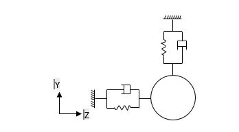
In order to calculate spring coefficient on the support element, the evaluation stage of the present study follows to the design calculation of journal bearing databook (Someya, 1989). It is assumed that 2 lobe bearing type is used and the characteristic data of bearings can be calculated according to the design procedures of databook. The dimensionless parameter called Sommerfeld number is defined in Equation 3.32 as
S = (1)
Where, = viscosity of lubricant
N = rotational speed (s-1)
Dc = diameter of crankshaft main journal (m)
L = length of crankshaft main journal (m)
= clearance ratio
W = bearing load (N)
Table
5.2. Control Factors for Vibration Improvement
Before starting the experimental design process, the crankshaft simulation model is firstly validated with experimental results in terms of dynamic characteristics (Pyae Sone et al., 2015). There are several control factors for the design parameters which could be used for the test in crankshaft structure modification. The level of the vibration depends on many design parameters. Geometrical parameters can be considered mainly such as crankpin diameter, main journal diameter, width of web, web thickness, pulley diameter, flywheel flange diameter and width of counterweight. Apart from design parameters, material properties such Young’s Modulus has considerable effect on the stiffness. Therefore, eight factors assigned in orthogonal array of experimental design. The design parameters which has been selected for the analysis are illustrated in Figure
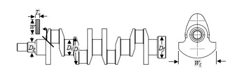
While selecting the parameters, the developed optimization of the crankshaft has to ensure that it gives no changes to the engine block and functions of an engine. To consider the design for optimization of the crankshaft, the technique of optimization using design on experiment is applied. In addition, the optimized crankshaft was expected to be interchangeable shape with the original crankshaft.
Table
Findings
6.1 Simulation in Experimental Runs
Firstly, a validated crankshaft structure model is built up using the setup of the original values for all input parameters in MSC NASTRAN/PATRAN. Total 18 models of crankshaft structure are generated according to the arrangement of parameters in orthogonal array of simulation to initiate the experimental runs. Frequency modal analysis is conducted for all simulation runs. Figure
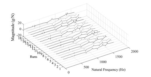
Of the total 18 runs, all simulations have been completed successfully together with both modifications in material status and geometrical development. Since the analysis becomes tractable and the laboratory test follow the Gaussian distribution. The mean square response,
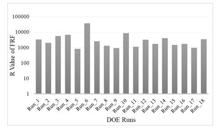
Due to structural modifications, various vibration levels are generated with respect to each crankshaft model. The area under frequency response function (FRF) graph describes the vibration response of the specified node. After computing FRF data, vibration responses are calculated to observe the vibration level of each crankshaft experimental model. Based from these responses, optimum parameters can be determined by using Taguchi method.
6.2. Influence of Control Factors for Parameter Design by Using DOE
The level of optimum parameter set points are the set point with the highest Signal to Noise ratio. These levels should provide the optimum response with the minimum effect due to noise. The data is generated from the simulated space defined by the factors and the range of their levels. The sensitivity for each control factor is higher due to larger changes of level of the S/N ratio value. On the other hand, the larger changes of level S/N ratio value means that reduction of vibration level is better for the reliability of the crankshaft. The control factor plots which factor levels are the best setting for increasing the Signal to Noise ratio is illustrated in Figure
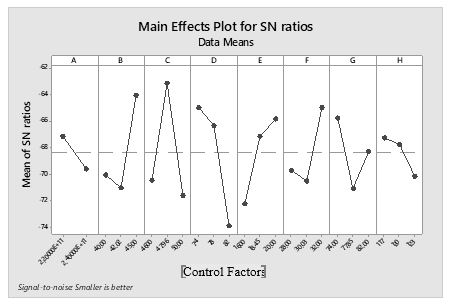
The horizontal axis is defined as a level of each control factor; vertical axis is defined as S/N ratio average of level. The optimum factor set points are those control parameters set points with the highest average Signal to Noise levels, and A1 (Young’s Modulus), B3 (crankpin diameter), C2 (main journal diameter), D1 (width of web), E3 (thickness of web), F3 (crankshaft end diameter), G1 (flywheel flange diameter) and H1 (width of counterweight). The number following the alphabet stands for the level of the optimum control factors. Regarding on the response graph, control factor C (main journal diameter) obtained the highest S/N ratio and is the most sensitive control factors for the optimization of the crankshaft.
Table
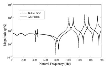
In a linear mechanical system. the ratio of response to input of the Fourier transform within the time domain can be defined as the frequency response function (FRF). When the fundamental resonance natural frequency was examined, a signal was applied as sinusoid waveform to transmit the identical vibration energy harvester with the same natural frequency. Afterwards, the crankshaft structure experiences a resonance causing high displacement amplitude. The vibration energy created by the excitation to the crankshaft was transferred by the piezoelectric sensor into electric energy signal transported by alternative current which can be expressed in LMS FFT analyser. The comparison of FRF of original and the newly developed crankshaft obtained from MSC NASTRAN is shown as in Figure
The vibration energy of a crankshaft which was converted into frequency response is shown in Fig 6, not only the levels of both transfer functions are reduced, but also the natural frequencies were shifted towards a higher frequency domain. From this FRF graph, mean square response R can be evaluated which is the area under the response spectral density curve (Curtis et al., 1971). Hence, it is found that the total average vibration response level in terms of R value is improved 38% within the total frequency range from 0 to 1600 Hz.
Conclusion
Structural modifications are considered with geometrical parameters as well as material characteristics. Eight control factors with different levels are selected in orthogonal array to construct experimental design. The responses are obtained in terms of FRF graphs to evaluate influencing factors with optimum level. Our study leads to the following conclusion;
Experimental designs are carried out by Taguchi method and total of 18 simulation runs are performed successfully under specified boundary condition in MSC NASTRAN/PATRAN.
A total of 38% of vibration response level are reduced for the optimized design crankshaft model compared to the original one. As a result, main journal diameter is the most influence factor for the crankshaft vibration response level.
Not only the frequency response of optimum model is reduced the natural frequencies are also shifted towards a high frequency domain.
Hence, a methodology is proposed to improve the vibration response level based on frequency response of crankshaft structure. The larger changes of signal to noise ratio value (S/N) means that the lesser the vibration response, which is better for the durability of the crankshaft. The optimum parameters are obtained. In the study, it is found that the initial values of Young’s Modulus and main journal diameter are still the best. A further work will focus on the combination of algorithms in neural network together with Taguchi method. In this manner, an additional precision of parameter modification would be possible.
Acknowledgments
All the tests were performed and mainly supported by the Intelligent Dynamics & System iKohza, Department of Mechanical Precision, Malaysia-Japan International Institute of Technology (MJIIT), Universiti Teknologi Malaysia, Kuala Lumpur.
References
- Abu, A., Aung, L. M., Sahekhaini, A., Zetty, R. M. S., & Pyae Sone, S. (n.d.). On the Improvement of Vibration Level of Crankshaft System Using Design of Experiment.
- Abu, M. Y., & Jamaludin, K. R. (2013). Application of Mahalanobis-Taguchi System on Crankshaft as Remanufacturing Automotive Part: A Case Study. Advanced Materials Research, 845, 883–888.
- Albers, A., Leon-Rovira, N., Aguayo, H., & Maier, T. (2009). Development of an engine crankshaft in a framework of computer-aided innovation. Computers in Industry, 60(8), 604–612.
- Approach, T., Jassi, J. S., Mohammad, A., Singh, D. P., & Jafri, H. Z. (2015). Machining parameter optimization using Machining parameter optimization using Taguchi Approach. International Journal of Advanced Manufacturing Technology, 3(July), 1–6.
- Baloni, B. D., Pathak, Y., & Channiwala, S. A. (2015). Centrifugal blower volute optimization based on Taguchi method. Computers and Fluids, 112, 72–78.
- Burdzik, R., & Dolecek, R. (2012). Research of Vibration Distribution in Vehicle Constructive, VII(4), 16–25.
- Cevik, M. C., Rebbert, M., & Maassen, F. (2010). A New Approach for Prediction of Crankshaft Stiffness and Stress Concentration Factors, 1–20.
- Curtis, Allen, J., Tinling, N. G., & Abstein, H. T. (1971). Selection and Performance of Vibration Tests (Vol. 8). The Shock and Vibration Information Center.
- Harris, L. N. (1989). Taguchi techniques for quality engineering, Philip J. Ross, Mcgraw-hill book company, 1988. Quality and Reliability Engineering International, 5(3), 249–249.
- Kakade, P., & Pasarkar, M. D. (2015). Analyzing and Identifying Various Approaches for Crankshaft Failures. Journal of Multidisciplinary Engineering Science and Technology (JMEST), 2(2).
- Mahendrakar, S., & Kulkarni, P. R. (2016). A Review on Design and Vibration Analysis of a Crank shaft by FEA and Experimental Approach, 1(11), 146–149.
- Montgomery, D. C. (2012). Design and Analysis of Experiments (Eighth). John Wiley & Sons, Inc.
- Pyae Sone, S., Moe, A. L., Abu, A., Nyein, O. K., Rohaiza, Z., & Sahak, M. (2015). Expermental Verification of Parameters in Automobile Modelling for Vibration Analysis. Proceedings of Malaysia-Japan Joint International Conference 2015 (MJJIC2015), 1–6.
- Someya, T. (1989). Journal-Bearing Databook. (T. Someya, Ed.). Berlin, Heidelberg: Springer Berlin Heidelberg.
- Taguchi, G., & Konishi, S. (1987). Taguchi methods, orthogonal arrays and linear graphs: Tools for quality engineering. American Supplier Institute, 35–38.
- Tanyildizi, H., & Şahin, M. (2015). Application of Taguchi method for optimization of concrete strengthened with polymer after high temperature. Construction and Building Materials, 79, 97–103.
- Tavakkoli, M., & Moallem, M. (2014). A New Implementation of Taguchi’s Method. International Journal of Engineering and Applied Sciences, 5(06), 24–34.
- Zetty, R. M. S., Aminudin, B. A., Aung, L. M., Khalid, M. K., Norfazrina, H. M. Y., & Raihan, N. M. R. (2015). Investigation of Sensitivity Effect Based on Mass and Stiffness Modification in Automobile Crankshaft. Applied Mechanics and Materials, 752–753, 839–844. http://doi.org/10.4028/www.scientific.net/AMM.752-753.839
Copyright information

This work is licensed under a Creative Commons Attribution-NonCommercial-NoDerivatives 4.0 International License.
About this article
Publication Date
17 May 2019
Article Doi
eBook ISBN
978-1-80296-061-7
Publisher
Future Academy
Volume
62
Print ISBN (optional)
-
Edition Number
1st Edition
Pages
1-539
Subjects
Business, innovation, sustainability, environment, green business, environmental issues
Cite this article as:
Moe, A. L., Bin Othman, N. A., Kyaw Nyein, O., Sahekhaini, A. B., Bin Abu*, A., & Sone, S. P. (2019). Design Of Experiment Approach On Vibration Characteristics In Automobile Crankshaft. In M. Imran Qureshi (Ed.), Technology & Society: A Multidisciplinary Pathway for Sustainable Development, vol 62. European Proceedings of Social and Behavioural Sciences (pp. 80-91). Future Academy. https://doi.org/10.15405/epsbs.2019.05.02.8