
Evaluation Of Marker Based Reference System For Head Pose Detection

Abstract
This research paper builds upon the modification of the existing algorithms introduced in the past several years and proposes/develops various techniques to significantly improve the functional performance for Marker-based Head-Pose Estimation. This research paper basically focuses on Marker-based point-to-point matching technique to extract Head-Pose information in real time. Several points on the Marker are detected in image plane and are then matched with the precalibrated correspondent 3D points of the markers which estimate the position and orientation of the visible markers in the image. Furthermore, a bundle adjustment is done to acquire the pose by using sufficient number marker points from the image in the exactly pre-known formation. Finally, pose of specific markers-combination is transformed into Head-Pose. Firstly, a commercially available offline software called Photo modeller is been used for the statistical, scalable and compact formation of the Head-Model (Introduced based on the appearance and 3D geometric information). This representation, achieved from offline learning process by statistical analysis of the Head-Model is used at run-time during the matching and estimation process for limiting the hypothesis by incorporating the camera-image and 3D geometric consistency constraints. This allows controlling the effect of the complexity of the 3D Head-Model on the run-time performance. Finally, the most concerned part of this paper is the accuracy and precision of the Head-Pose. For which, the physical markers and combinational 3D marker-points (for the used algorithm) are been modified and then pre and post modification results are compared.
Keywords: Head-Pose EstimationPhoto Modeller3D Head-Model3D Marker-pointsADASSpACiAL
Introduction
The main topic of this dissertation is computer vision-based Human-Head Motion capture, generate Head-Model and finally real-time Human Head-Pose Estimation. It introduces the motivation behind the work, the research questions that have been answered and the research methodology used.
Motivation and Overview
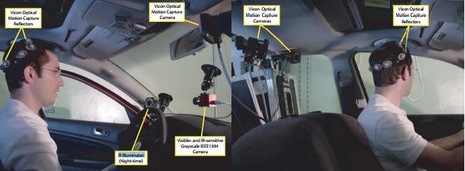
Computer vision-based head and complete human motion capture is a well-established area of research that has seen a lot of activity over the past two decades as a survey shows (Adelson & Bergen, 1991). The activity is motivated by a wide range of applications for robust motion capture, and the high complexity of the task gives rise to many still unsolved problems. The best-known approach which is also very convenient in terms of processing due to the coded identification of the landmarks, for capturing head motion is the use of markers as random landmarks. Cameras get the images of the markers in real-time and identify the markers, and a three-dimensional point cloud is generated. This approach has several drawbacks: the markers are invasive and can cause experimental artifacts, and recreating motion from the point cloud usually involves time- consuming manual post-processing (Kato & Billinghurst, 1999; Klein & Murray, 2006; “A.R.T. Advanced real time tracking.” n.d.).
However, in practice robust object tracking in real-time is quite challenging and remains an open problem. Reasons for that are manifold. First of all tracking systems require an initialization, i.e. providing the system with the initial poses of the object or camera. Once tracking is started, rapid motions causes’ image features to undergo large motion between frames which can cause visual tracking systems to fail. Furthermore, it can cause motion blurred images where extraction of feature correspondences may fail. The lighting during a shot can change significantly; specular reflections may confuse the tracker. Finally, complete or partial occlusions as well as large amounts of background clutter may result in tracking failure. Once tracking fails the system must be re-initialized in the same manner. Therefore, one of the main challenges in tracking remains automated initialization and recovery. Systems that are initialized by hand or require the camera to be very close to a specified position are not desirable options for automotive head tracking solutions.
The lack of a fast, reliable and automated initialization method is one of the main crucial problems that make many current tracking systems useless in the industry as well as in computer aided minimally invasive surgery. This has led to increased popularity of fiducial- or marker-based tracking system such as ARToolKit, or A.R.T. system, where the 3D tracking task is simplified to overcome the tracking limitations by detecting predefined artificial markers in every frame independently without constrains on camera pose. Using markers increases robustness and reduces computational requirements. However, it requires engineering the environment, which is not accepted in many industrial applications by the end-users and is sometimes even impossible, e.g. in outdoor environments. This has led to the development of systems in hybrid configurations involving expensive magnetic or inertial trackers. The difficulty of overcoming the vision based tracking limitations as described above stems from the need for fast and robust detection and pose estimation of objects in the scene from a single image without priors on the pose.
Rolling Shutter (Bundle Adjustment)
In bundle adjustment, a key modelling assumption is that each image is associated with one single camera pose. For a moving camera to satisfy the assumption, the whole image has to be captured at single time instance, referred to as the camera having a global shutter. This is the case for the CCD sensor which has been the dominant sensor in digital imaging. Due to cost and energy efficiency the CCDs are gradually being replaced by the CMOS sensor.
The rolling shutter camera on the iPhone takes 30ms to capture a complete image. Whereas in video mode the lens has a horizontal angle of view of 46.7◦ and the video format is 720p. For a horizontal panning motion where the camera is turned 90◦, the following table of rotation speeds and pixel displacements can be composed:
Problem Statement
The problem addressed in this research paper is the automatic recovery of the three- dimensional pose of an object of interest from a real-time camera image (Dementhon & Davis, 1995; Hartley & Zisserman, 2003; Nister, 2003; Pollefeys, Koch & Gool, 1998; Vacchetti, Lepetit & Fua, 2004)
Tracking objects through image sequences is one of the fundamental problems in computer vision, and estimating the motion and pose has been an area of research for many years (Davison & Murray, 2002; Drummond & Cipolla, 2002; Genc, Riedel, Souvannavong, Akinlar, & Navab, 2002; Klein, 2006).
In many recent applications ranging from Robot Navigation, Surveillance to Augmented Reality real-time performance is of critical importance. Many reliable solutions have been proposed for real-time pose estimation given correspondences and feature-based 3D tracking. Traditional tracking approaches make use of a strong prior on the pose for each new frame. Imposing temporal continuity constraints across frames increases the quality and robustness of the results. During the last years vision based tracking systems have reached a maturity level capable of tracking complex 3D objects very accurately.
Research Questions
How to develop, modify and evaluate a real-time marker-based computer vision Head-Pose Estimation System?
This can be further categorized into several sub-questions:
Q1 Current Situation:
-
What is the state of the art in the field of computer vision-based Head-Pose Estimation?
Q2 Data acquisition:
-
How can three dimensional information about the subject, be recovered from single camera video/images in real time?
Q3 Estimation:
-
How can an underlying Head-Model be recovered more accurately from the three dimensional reconstructed data?
-
How can the pose estimation algorithm be applied over the available data?
-
How to modify the system in case of undesirable accuracy and precision?
Q4 Performance:
-
How should the performance of the whole system be evaluated?
-
How can the proposed pose estimation approach be used in a practical application?
Purpose of the Study
The Purpose of this research was to ensure the safety of the driver and usage in various other applications of ADAS (Advanced Driver Assistance System). The main aim of this research is to develop a marker-based Head-Pose Estimation System in real-time and also study the accuracy and precision of the system.
Research Methods
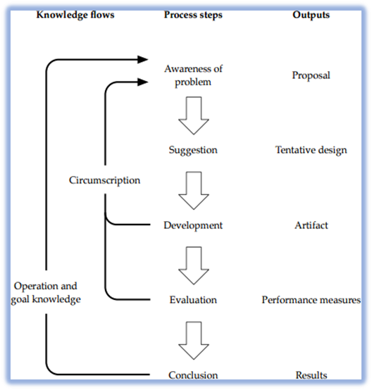
Computer vision techniques are constructed artifacts, and in that sense computer vision is a science of the artificial, or a design science. Consequently, the design science research methodology (Kuechler, Vaishnavi, & Kuechler Sr, 2007) was used in this research paper. As can be seen in figure
Awareness of problem
The research effort originates from the awareness of an interesting problem. This awareness can stem from new developments in the field, or by studying related disciplines from which existing methods can be applied in novel ways. The result of this phase is a proposal for a research paper.
Suggestion
Existing knowledge or the theoretical base of the problem area is used to suggest possible solutions to the problem. This knowledge was acquired through a literature review of the field, and used to formulate a tentative design for a solution to the problem. This also involves making necessary assumptions about the solution and limiting the scope of the task to be manageable within the constraints of the project. Research questions
Development
During the development phase the tentative design evolves into a complete design of the solution. An artifact is implemented based on the design. Algorithm was modified to answer
Evaluation
The proposal defines a number of criteria for expected behaviour of the artifact. In the evaluation phase the performance of the artefact is assessed and compared against those criteria. Deviations from the expected behaviour is analysed, and hypotheses are formed about the shortcomings of the current solution. As the circumscription arrows in figure
Conclusion
Eventually the research effort is concluded, at which point the artifact still might not fully satisfy all expected behavior, but is considered good enough. The results are consolidated and the new knowledge gained is documented. Anomalous behavior can serve as starting points for new research efforts. This phase resulted in a tentative answer to
Contribution
The main contributions of this research effort are:
Evaluation of the Calibration procedures (both Intrinsic and Extrinsic)
Evaluation of Head-Tracker System‘s accuracy and precision
Hardware setup to perform tests for evaluating Position and Orientation accuracies and precisions
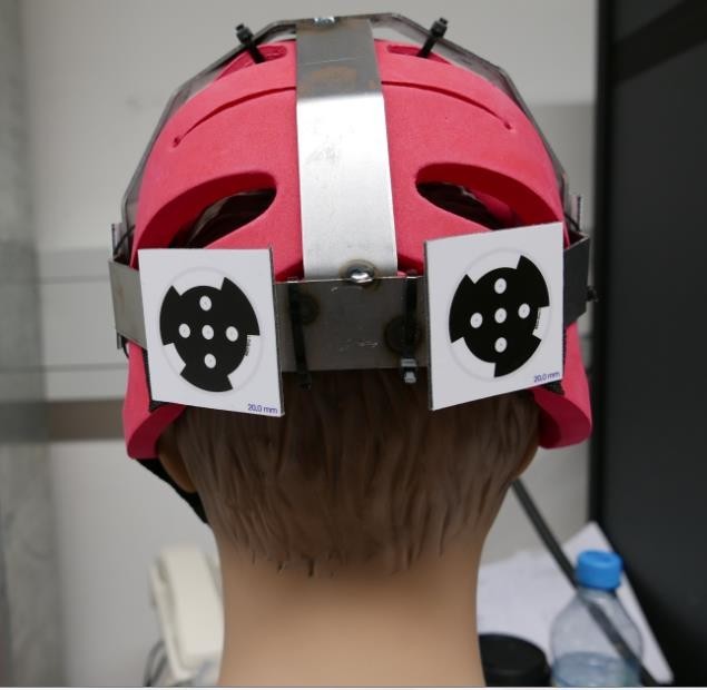
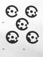
Designing a Super-Marker by using multiple MCMXT markers to attain desired results
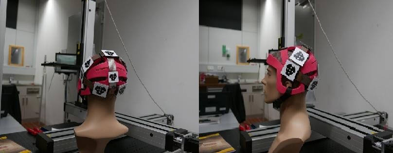
Structure of the Helmet and Head-Model, allowing the feature points of the driver to keep visible for other camera systems.
A General-Purpose computation on Graphics Processing Units (GPGPU) implementation of a fully parallel thinning algorithm that is well suited for use in Head-Pose estimation, and achieves real-time performance.
A pose estimation method based on constructing a Head-Model by using a tool named
Photomodeler based on the markers placement over the Helmet. The configuration of the Head-Model is independently structured in an offline tool, which overcomes the limitation of processing time, geometrical structure of various drivers’ heads and provides a pretty accurate 3D model. The method achieves real-time performance on any possible model.
Findings
The tool used in this project for calibrating the cameras is named as SpACiAL (Semi-Automatic Camera Calibration)
Two patterns used for the calibrations which are mentioned below:
Intrinsic Calibration Pattern.
Extrinsic Calibration Pattern.
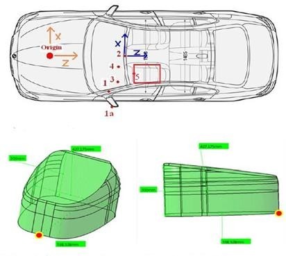
3D Head Model
Generating a 3D Head-Model by using multiple markers over the helmet of the driver is really important in terms of knowing the exact relative positions of the markers. Coordinate values of this model will be further used by the pose estimation algorithm as 3D correspondence points of the markers and perspective matching of the these points will be done with the image points visualized by the camera.
The most vital point at this stage was to identify a way to elaborate the head model that could either have been done manually by measuring the relative distances and orientations of the markers or by using an independent offline tool to visualize and generate a head-model. This task was first done manually for some simple structures or formations of markers placement. But unfortunately to achieve the same level of accuracy for more complex or real head structure, the manual approach failed. So, a tool called “PhotoModeler” was employed up to generate an accurate Head-Model in an automated manner.
Camera Calibration Using PhotoModeler
PhotoModeler Scanner is a 3d scanner that provides results similar to a 3d laser scanner. Scale-independent object modeling - model small objects or big scenes (“PhotoModeler Scanner,” n.d.). Usual calibration algorithms are used by PhotoModeler for the cameras, not very different from the techniques used by SpACiAL software. Various numbers of specified patterns containing dot-markers are used from several different views, for the intrinsic calibration of the camera. These markers are automatically detected, marked and referenced by the software, whereas in case of other markers it has to be done manually or by setting up a target-code.
Pose Estimation
Head pose estimation is an important part of the human perception and is therefore also relevant to make interaction with computer systems more natural. However, accurate estimation of the pose in a wide range is a challenging computer vision problem. It basically gives the orientation and position of an object in the relative coordinate system.
The requirement was to achieve a goal of ±1degree and ±1mm of accuracy in orientation and position within the given Head-Box, respectively (Martin, Camp & Stiefelhagen; 2014).
MXT MT Multicam
MXT_MT_Multicam implements the Fraunhofer IOSB MXT library. It detects badges in the provided image streams and forwards the image streams to the next plug-in. In addition it adds an output image per input image
Like point to point matching and triangulation.
Conclusion
A marker-based Head-Pose Estimation system was designed for the safety of the driver and usage in various other applications of ADAS (Advanced Driver Assistance System), by Fraunhofer Institute, the whole package containing the calibration tool SpACiAL, the hardware setup including cameras and the SDK (DevEnviro) used for detection and estimation of the head-pose. The fundamental idea of this research was to evaluate the system in the lab and after achieving the desired accuracy and precision of the marker-pose, the system had to be implemented in a practical scenario. By setting up the complete system i.e. the construction of the hardware structures and mounting the markers over a helmet, various tests were conducted for estimated positions and orientations of the head The results were totally unacceptable in terms of both accuracy and precision which were widely deviated from the required results after extraction and evaluation of the recorded data of the system. Then the whole system was then modified, starting from the designing of new markers which was the combination of two markers called “super-marker”, further moved to modification of outlook of the SDK as per the requirements of the tests, the code was modified to design new markers and algorithm was enhanced to allow to take the data in the form of newly designed markers and the pose was estimated. The 3D geometry of the helmet was structured using an independent software “Photomodeler”, and the data resulted from there was forwarded to the modified algorithm in the SDK. At this point, the accuracy error was reduced above 70% as compared to the results observed from the available system. After the achievement of maximum possible accuracy from the modified system, the marker-pose was transformed to helmet-pose and further to head-pose.
Recommendation
According to my analysis and experience, I would recommend using this modified system if the required accuracy level is ±4mm and ±4.5° along with high precision of ±0.6mm and ±0.2°, also where the robustness is not a highly required parameter. In case of more accurate applications try different system with high accuracy, precision and robustness.
Future Perspectives
To further increase the level of accuracy, two plugins were designed in order to merge/split the images coming from two cameras and tried to implement the epipolar technique, which was not in the end implemented and tested. Whereas trying this approach along with calculating highly accurate 3D model data might make it possible to achieve the required accuracy.
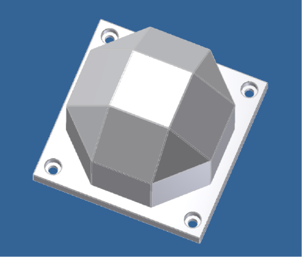
The 3D model of the helmet also has a great influence over the accuracy and hence several methods were used to get the accurate model-structure of the helmet. A test was constructed to evaluate the accuracy of the 3D head-model by using the orthogonal target, which was designed over CAD and printed out with an accurate 3D printer as shown in figure
References
- Adelson, E. H., & Bergen, J. R. (1991). The plenoptic function and the elements of early vision.
- Davison, A. J., & Murray, D. W. (2002). Simultaneous localization and map-building using active vision. IEEE Transactions on Pattern Analysis & Machine Intelligence, (7), 865-880.
- Dementhon, D. F., & Davis, L. S. (1995). Model-based object pose in 25 lines of code. International journal of computer vision, 15(1-2), 123-141.
- Drummond, T., & Cipolla, R. (2002). Real-time visual tracking of complex structures. IEEE Transactions on pattern analysis and machine intelligence, 24(7), 932-946.
- Genc, Y., Riedel, S., Souvannavong, F., Akinlar, C., & Navab, N. (2002). Marker-less tracking for AR: A learning-based approach. In Mixed and Augmented Reality, 2002. ISMAR 2002. Proceedings. International Symposium on (pp. 295-304). IEEE.
- Hartley, R., & Zisserman, A. (2003). Multiple view geometry in computer vision. Cambridge university press.
- Heuristic. (n.d.) “Fraunhofer IOSB Inst. Website” https://www.iosb.fraunhofer.de.
- Heuristic. (n.d.) “PhotoModeler Scanner,” https://photomodeler.com/products/scanner/default.html
- Heuristic. (n.d.). “A.R.T. Advanced real time tracking.” https://www.ar-tracking.com.
- Kato, H., & Billinghurst, M. (1999). Marker tracking and hmd calibration for a video-based augmented reality conferencing system. In Augmented Reality, 1999. (IWAR'99) Proceedings. 2nd IEEE and ACM International Workshop on (pp. 85-94). IEEE.
- Klein, G. (2006). Visual tracking for augmented reality (Doctoral dissertation, University of Cambridge).
- Klein, G., & Murray, D. W. (2006, September). Full-3D Edge Tracking with a Particle Filter. In BMVC (pp. 1119-1128).
- Kuechler, W., Vaishnavi, V., & Kuechler Sr, W. L. (2007, May). Design [science] research in IS: a work in progress. In Proceedings of the second international conference on design science research in information systems and technology (DESRIST 2007) (pp. 1-17).
- Martin, M., Van De Camp, F., & Stiefelhagen, R. (2014, December). Real time head model creation and head pose estimation on consumer depth cameras. In 3D Vision (3DV), 2014 2nd International Conference on (Vol. 1, pp. 641-648). IEEE.
- Nister, D. (2003, June). An efficient solution to the five-point relative pose problem. In Computer Vision and Pattern Recognition, 2003. Proceedings. 2003 IEEE Computer Society Conference on (Vol. 2, pp. II-195). IEEE.
- Pollefeys QR, M. (1998). Koch qL. V. Gool. Self - Calibration and Metric Recon struction in spite of Varying and Unknown Intrinsic Camera Parameters.
- Vacchetti, L., Lepetit, V., & Fua, P. (2004). Stable real-time 3d tracking using online and offline information. IEEE transactions on pattern analysis and machine intelligence, 26(10), 1385-1391.
Copyright information

This work is licensed under a Creative Commons Attribution-NonCommercial-NoDerivatives 4.0 International License.
About this article
Publication Date
17 May 2019
Article Doi
eBook ISBN
978-1-80296-061-7
Publisher
Future Academy
Volume
62
Print ISBN (optional)
-
Edition Number
1st Edition
Pages
1-539
Subjects
Business, innovation, sustainability, environment, green business, environmental issues
Cite this article as:
Sajeel, M., Adeel, M., & Nabeel, M. (2019). Evaluation Of Marker Based Reference System For Head Pose Detection. In M. Imran Qureshi (Ed.), Technology & Society: A Multidisciplinary Pathway for Sustainable Development, vol 62. European Proceedings of Social and Behavioural Sciences (pp. 153-163). Future Academy. https://doi.org/10.15405/epsbs.2019.05.02.14