
The Role Of Mathematical Models In The Evaluation Of The Knee Injuries


Abstract
This article studies the effects of mechanical lateral impact on the knee joint and tibial plateau, with pelvic limb supported and unsupported on the ground, using a mathematical model in AUTOCAD and transposed in COSMOS program. The effects were evaluated at the level of the knee in both supported and unsupported situations. The principle of the mathematical model of the knee joint was to decompose each joint component in thousands of finite elements. The most important conclusions were obtained when we analyzed the mathematical model of the proximal third of the tibia in the lateral impact. The results of the model analysis suggest that a lateral impact on the knee, with a lower limb support at a speed of 20-30 km/h, will damage only ligaments; as speed increases, bone lesions will appear and force dissipates in the femoral condyle, where subchondral fracture are appearing. If the action of the traumatic agent generates the rupture of the anterior external cruciate ligament, the effect of the maximum force applied on the knee is dissipating, and there is no longer transmitted to the bone. Ligament injury always occurs before the appearance of the bone fracture. The only exception is fracture-dislocation when the movement of the bone fragments is associated with a secondary cruciate ligament injury. The mathematical models can fairly predict the type of the fractures involving the bones of the knee joint.
Keywords: Mathematical modeltibiacruciate ligamentsknee injury
Introduction
In 2010 we created a mathematical model which can predict the effects on the tibial plateau when exposed to longitudinal forces generated by the impact with different masses (Ungurianu, 2010a). This model can be used to demonstrate the formation of the type I-VI Schatzker fractures. This mathematical model also allows us a wide variety of modeling under various impacts angles and planes (Ahlberg, Nilson & Walsh, 1967, pp. 125-180). This study evaluates how the tibial plateau behaves on a lateral impact, with pelvic limb supported and unsupported on the ground.
Problem Statement
This study was initiated after we noticed that from 55 cases with fractures of the proximal third of tibia which were treated with orthopedic solutions or percutaneous screws, 15% accused a laxity and instability of the knee, 3-4 months after the first intervention. To complete recovery, some of these needed to associate a daytime immobilization of the knee which has further reduced the effects of instability. Following these observations, we attempted to develop a mathematical model to predict the behaviour of ligaments and bone structures of the knee in proximal tibia fractures.
Research Questions
Our research tried to estimate if a mathematical model based on the Finite Element Analysis (FEA), also known as Finite Element Method (FEM), could anticipate the behaviour of the cruciate ligaments of the knee in fractures of the upper third of the tibia. This analysis was based on the discretization method: the model body was divided into an equivalent system of many smaller bodies or units (finite elements), interconnected at points common for two or more elements (nodes or nodal points), and/or boundary lines, and/or surfaces. The results generated by the achieved model would be closer to the real life results when the number of finite elements is bigger. We analyzed the behaviour of the cruciate ligaments in several types of fractures of the upper third of tibia secondary to several types of impact forces.
Purpose of the Study
The purpose of the study was to identify the effects of a lateral impact on the knee bones and ligaments, using a mathematical model. The effects were analyzed in two settings – first, when the lower limb was unsupported and second, when the lower limb was fixed on the ground. We have analyzed the effects of the impact on both knee bones – tibia and femur, and on the cruciate ligaments of the knee: anterior external and posterior internal.
Research Methods
We used the mathematical model of the knee joint, which was formed from the decomposition of each part of the joint in thousands of tetrahedral finite elements (Antonescu, 2008, pp. 368-374). The tetrahedral geometry was used because it has a similar aspect when compared to the Haversian bone cells. The tips of these virtual bone cells are called nodes. A node is common to several neighboring finite elements (4, 5 or more). Forces acting on the body are distributed only to these nodes, and they are called nodal forces (Brunner et al., 2009). The movement of the nodes will be made in directions that make the resulting potential energy produced by deformation of the entire structure to be minimal. Once we have determined the directions of the nodes movements, the mechanical tension inside the finite elements, such as the specific deformation of them (tracts of fractures), could be easily calculated. These results were approximate but could be considered to be similar to the tracts generated in the real bones (Micula, 1978, pp.35-37).
Applying a force on the system represented by the knee bones has the same mechanical effects of a small blunt object with a small mass and high impact speed or an object with a large mass and small impact speed. The common element is the kinetic energy of the object which is transformed into potential energy of deformation, causing the fracture (Böhmer, 1974).
Hitting a body has two mechanical effects: a reversible (elastic) deformation of the body and the breakage (irreversible deformation) (Ungurianu, 2010b). The ratio in which the kinetic energy of the blunt body is divided between these two effects is difficult to determine, especially in biological structures containing tissues with very different mechanical properties (Sard, & Weinstraub, 1971, pp.95-96).
We used a mathematical model obtained through the specialized COSMOS program, submitted to side impact with the lower limb unsupported and supported (Botez, 2008, pp. 55-56). First, the model of the knee joint and bones has been generated in AutoCAD and then, using the COSMOS Works program, it has been transformed into a mathematical model with 15230 finite elements, 7674 nodes, and 92088 degrees of freedom. The model generated with COSMOS Works has a finite number of elements of tetrahedral type. The distribution of the finite elements to the three bone structures of the knee joint was as follows: femur – 3425 elements, tibia – 3135 elements, fibula – 1757 elements. The rest of the finite elements were assigned to the osteosynthesis materials used in the study. COSMOS Works imported loads from COSMOS Motion and COSMOS Flo Works. The program allowed applying forces and pressures as many times as desired. COSMOS Works superimposes all pressures, forces, and remote loads.
Findings
The study of lateral impact, with the lower limb unsupported
When developing the mechanical model of the knee we observed that fractures occurring in a knee injury when lower limb is unsupported need a higher speed of impact to give a shear and a break between finite elements of the mathematical model (Omura, & Callori, 1999, pp.112-114).
At speeds below 50 km/h the impact that takes place below the knee causes destruction of ligaments, and bone mechanical tensions remain at subcritical values (without causing fractures of the tibial plateau) (Mustonen et al., 2008). In these cases, we appreciate that the mass of impacting body should be approximate one ton and the speed of impact was the one who determines the nodes elongations and their rupture.
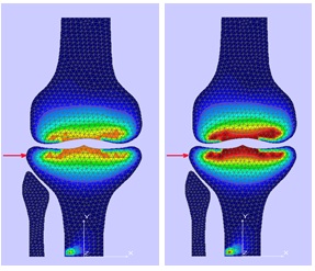
We modeled four cases in which the mass of impact was the same (approx. one ton) but the speed was different. In the first case, the speed was 20 km/h, and the mathematical model behaved as an elastic complex, which suffered only elongations in the tetrahedral breaking nodes (Fig. 1 left). The areas of maximum stretching, represented by yellow colour, and peripheral areas of tension represented by green colour, have no evidence of shear. Chromatic map of the mathematical model (Fig. 1 left) put to forces of 20km/h indicates that the bone resistance may counteract the action of the traumatic agent whatever the maximum force trauma triggered by the force of impact.
In the second case, we increased the speed to 40 km/h and we obtained an elongation of the knots without breaking them (Fig. 1 right); In this case, stretching areas are more intense but on a lower surface. It is possible that one or two nodes to be shearing (chromatic yellow map is more intense in certain nodes - can be seen from Table
The figures bellow show that the deformation tensions were only elastic, being associated with bone edema lesions.
![The mechanical stresses map in a mathematical model subjected to a traumatic agent acting
at a speed of 20km/h (left) and 40km/h (right)]](https://www.europeanproceedings.com/files/data/article/58/2159/MEPDEV2016FA094.fig.001.jpg)
We also have generated a table (Table
When the impact velocity was increased, the shear mathematical model was obtained. Thus, when the impact speed was 60 km/h, in addition to cruciate and collateral ligament rupture, we obtained a tibial plateau fracture - comminuted, mixed (Kayali et al., 2008). In another simulation with a higher speed of 80 km/h, the mathematical model was broken by shearing tibial nodes of tension, producing a comminuted fracture of proximal third tibia (Fig. 2) (Niculescu et al., 2010).
Also, in the unsupported foot impact at a high speed, the mathematical model of the femoral condyle was discretized (broken). Using the mathematical model we have observed shear at the junction of the tibia metaphysis and diaphysis with the probability of epiphyseal-metaphysis fracture (Cannada et al., 2008).
If in the Table
Side impact study regarding ligaments, with lower limb fixed on the ground
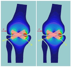
The mathematical model allowed us to evaluate how the cruciate ligaments are affected by the impact. In the original mathematical model we integrate the cruciate ligaments to take account of their position: anterior external and posterior internal (Fig. 3). Because posterior internal ligament is shorter and thicker, thus stronger, we anticipated that the anterior external cruciate ligament will tear first (Purghel et al., 2008). Simulations were made using a lateral impact, in which lower leg is supported. Impact energy causes the tensions in ligaments and bone structure request until the maximal strength of one of them is reached (Ungurianu, 2010c).
Depending on the movement of the upper joint, the ligament elongation is calculated based on the graphic lines presented in the Fig.
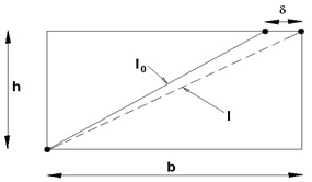
Length variation of the displacement is expressed as
where
The force applied on the ligament depends on many factors: patient age, sport, physical inactivity, prolonged immobilization etc. For organic materials similar to human bone composition there is a non-linear relationship between elongation and applied force expressed by a function of the following type: , where "k" is a stiffness coefficient (coefficient of "age") (Shen et al., 2009).
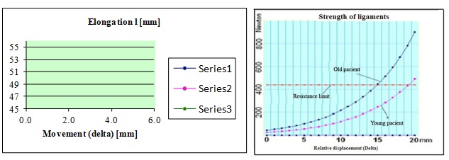
For young persons, under 35 years of age, who can sustain a ligament elongation of 25-30% of its length, k = 10 … 12. At an older age, over 35 years, where elongation is not more than 15-20% of length, k = 18 ... 20. F0 is a force equivalent to ligament stiffness in the relaxed state ("pre-stressing"). The coefficient
The results of the calculated ligament length, a value which was inserted into the formula of the force, and represented in the diagrams above, are listed in Table
The mathematical model was performed at different loads, depending on the k coefficient. Elongations of 30% were followed by a reversal to the original length in all young people but this reversal was present in only 17% of the individuals over 35 years. The breaking point, signalled by the force applied to the external femoral condyle was about 430N for both young and elderly at an elongation of about 20 mm for young people. In clinical practice, this suggests that a young patient will make an impact injury rather than a broken ligament injury, while an elderly person will be especially prone to a fracture than a ligament injury. If during the action of the traumatic agent, the rupture of the anterior external cruciate ligament occurs the maximum force acting on the knee is dissipated and is no longer transmitted to the bone.
Discussion
In the first type of simulation, the impact was in the lateral part of the knee and the knee supported the force of the traumatic agent. This case was associated with variable capsule-ligament and bone injuries depending on the speed of the impact. At the low speed we had only ligament damage and bone edema while at speeds of 60 km/h bone lesions were present - comminuted fractures Schatzker stage V-VI. At these speeds, there are mirror injuries at the femoral condyle level. This mathematical model can help us to understand how the action of traumatic agents is followed by a specific type of injury. In the translation of these results in clinical practice will suggest that a young patient will suffer a broken ligament injury rather than a bone injury, while an elderly person will be especially prone to fracture than a ligament injury. ;
Conclusion
When there is a lateral impact on knee, with a lower limb support at a speed of 20-30 km/h, only ligament damage will appear. At a speed of 50-60 km/h, bone lesions are appearing. As speed increases, the bone lesions will increase and force dissipates in the femoral condyle, where subchondral fracture are appearing. Breaking point – identified by a force applied to the external femoral condyle, was about 430N for both young and elderly, associated with a ligament elongation of about 20 mm for young people. If during the action of the traumatic agent, the rupture of the cruciate ligament occurs on the anterior external side, the maximum force acting on the knee is dissipating and is no longer transmitted to the bone. Ligament injury always occurs before the onset of the bone fracture. The only exception is when the movement of the dislocated secondary fragments of the fracture is associated with the cruciate ligament injury.
References
- Ahlberg, J. H., Nilson, E. N. & Walsh, J. L. (1967). The Theory of Splines and their Applications. New York: Academic Press.
- Antonescu, M. D. (2008). Patologia aparatului locomotor, vol. II. Bucureşti: Editura Medicală.
- Böhmer, K. (1974). Spline-Functionen. Stuttgart: B.G. Taubnev.
- Botez, P. (2008). Tehnici avansate şi biomateriale în ortopedie, vol. I. Iaşi: Editura Gr. T. Popa, UMF Iaşi.
- Brunner, A., Horisberger, M., Ulmar, B., Hoffmann, A. & Babst, R. (2010). Classification systems for tibial plateau fractures; Does computed tomography scanning improve their reliability? Injury, 41(2), 173-178. doi:
- Cannada, L. K., Anglen, J. O., Archdeacon, M.T., Herscovici, D. Jr. & Ostrum, R. F. (2008). Avoiding complications in the care of fractures of the tibia. J Bone Joint Surg Am., 90(8), 1760-1768.
- Shen, C., Ma, J., Chen, X. D., Dai, L. Y. (2009). The use of b-TCP in the surgical treatment of tibial plateau fractures. Knee Surg. Sports Traumatology Arthroscopy, 17(12), 1406-1411. doi:
- Sard, A. & Weinstraub, S. (1971). A Book of Splines. New York: J. Wiley.
- Micula, Gh. (1978). Funcţii spline şi aplicaţii. Bucureşti: Editura Tehnică.
- Mustonen, A. O., Koivikko, M. P., Lindahl, J. & Koskinen, S.K. (2008). MRI of acute meniscal injury associated with tibial plateau fractures: prevalence, type, and location. AJR Am J Roentgenol., 191(4), 1002-1009.
- Niculescu, B., Borza, I., Popescu, M. & Faur, C. (2010). Tratamentul chirurgical al fracturilor complexe de platou tibial. Revista de Ortopedie şi Traumatologie, SOROT 2010, 20(2), 319-322.
- Omura, G. B. & Callori, R. (1999). AutoCAD Ghid de referinţă. Bucureşti: All Educational.
- Kayali, C., Oztürk, H., Altay, T., Reisoglu, A. & Agus, H. (2008). Arthroscopically assisted percutaneous osteosynthesis of lateral tibial plateau fractures. Can J Surg., 51(5), 378-382.
- Purghel, F., Jemna, C., Anastasiu, A., Ciuvică, R. (2008). Leziuni osoase şi de părţi moi cauzate de implantele metalice. Revista de Ortopedie şi Traumatologie a Societăţii de Ortopedie Romano-Italo-Spaniole, Timişoara, 3/4 (13), 10-18.
- Ungurianu, S. (2010a). Tibial plateau fractures mathematical model to correlate agent force trauma. In ATEQUAL 2010, 15-18 July 2010 Iasi Romania, (pg 64-68). IEEE Computer Society.
- Ungurianu, S. (2010b). Fracturile treimii proximale de tibie (Unpublished doctoral thesis). Universitatea de Medicină şi Farmacie "Gr. T. Popa" din Iaşi, Iaşi.
- Ungurianu, S. (2010c). Ligamentoplastia în stabilitatea genunchiului post fractura platoului tibial. Jurnalul de Chirurgie.ro, 6(2), 145-149.
Copyright information

This work is licensed under a Creative Commons Attribution-NonCommercial-NoDerivatives 4.0 International License.
About this article
Publication Date
30 July 2017
Article Doi
eBook ISBN
978-1-80296-026-6
Publisher
Future Academy
Volume
27
Print ISBN (optional)
-
Edition Number
1st Edition
Pages
1-893
Subjects
Teacher training, teaching, teaching skills, teaching techniques,moral purpose of education, social purpose of education, counselling psychology
Cite this article as:
Ungurianu, S., Cojocaru, D., & Negru, R. D. (2017). The Role Of Mathematical Models In The Evaluation Of The Knee Injuries. In A. Sandu, T. Ciulei, & A. Frunza (Eds.), Multidimensional Education and Professional Development: Ethical Values, vol 27. European Proceedings of Social and Behavioural Sciences (pp. 801-811). Future Academy. https://doi.org/10.15405/epsbs.2017.07.03.95